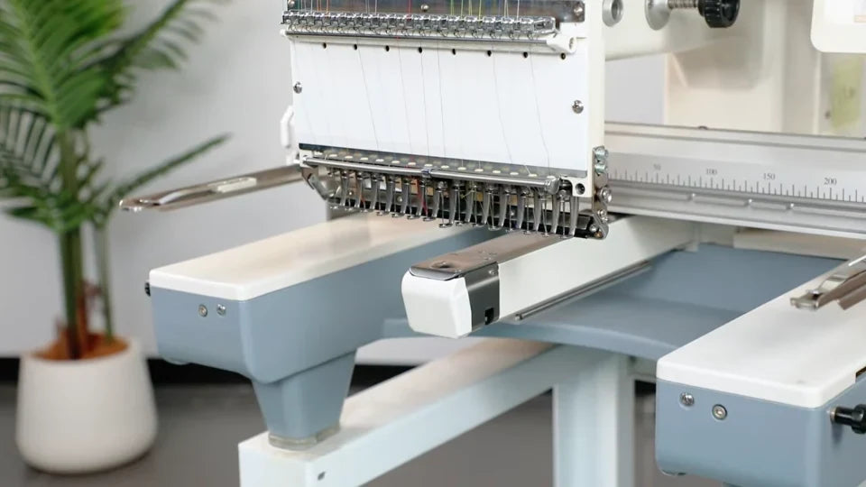
SEWTECHSupport Center 简体中文

Install and Adjust HoopSteady

Tool: HoopSteady

Watch on YouTube ↗

Overview

Set up HoopSteady with the machine stopped. Have a caliper, a metric ruler and a hex key ready. The video shows how to size both pairs of clamping blocks to the cylinder arm, check the fit, and extend the support beneath a larger hoop. Use your machine’s measured width. The 50 mm shown here is an example.

Step-by-step guide

1. Check the initial fit

Watch at 00:15

Slip the unadjusted support onto the cylinder arm and gently wiggle the front end. The demonstration shows some play before adjustment. This is the point to size the clamping blocks to your machine.

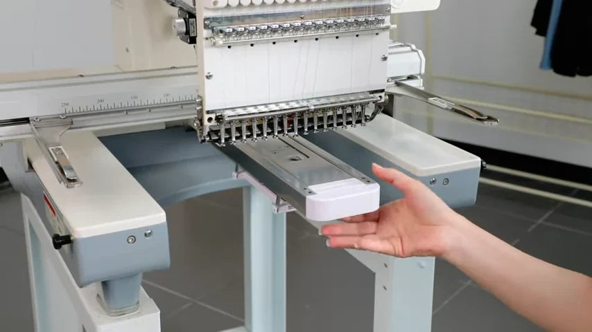
The underside of the support before adjustment.
Gently move the front end to feel for play at the cylinder arm.

2. Remove the support and measure the arm

Watch at 00:28

Take HoopSteady off the machine. Place the caliper’s outside jaws against the two sides of the cylinder arm at the mounting area. Record the width. The reading is about 50 mm (5 cm) in the video.

The support is clear of the cylinder arm, exposing the mounting area.
The caliper spans both sides of the arm. The arrow marks the example reading near 50 mm.

3. Align the ruler with the centerline

Watch at 00:59

Turn HoopSteady underside up and identify the centerline between the two rails. Lay the ruler across the blocks and align its 10 cm mark with the centerline as shown. Halve the width you measured. A 50 mm opening calls for 25 mm on each side of center, at the 7.5 cm and 12.5 cm marks in this example.
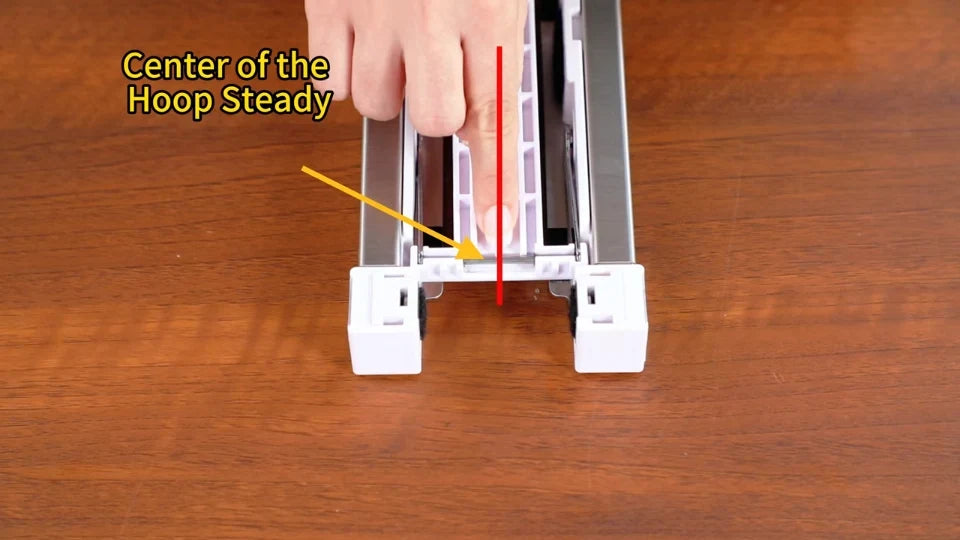
The vertical red line identifies the center between the rails.
The 10 cm mark sits at center. The dashed lines show the two edges of the 5 cm opening.

4. Set the first pair of clamping blocks

Watch at 01:22

Insert the hex key into the screw on the outer face of each white end block. Follow the Loose and Tighten arrows printed around the screw. Watch the block extend as you turn toward Tighten. Alternate sides and check that both inner faces are the same distance from the ruler’s center mark. Their total opening should match the measured arm width.

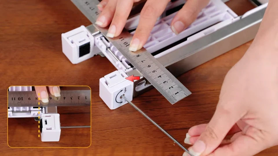
The adjustment screw is on the outside of the white end block. The inset shows the two turning directions.
Repeat the adjustment on the opposite end block while holding the ruler centered.
Check the opening at the two inner faces. The video marks 5 cm across.

5. Expose the extension-slide screws

Watch at 01:43

Keep the support underside up and pull the extension slide out until its two side access holes are exposed. Place the ruler across the second pair of blocks and align it to the same center reference.

The slide is pulled out from the main rails so the side screws can be reached.
Lay the ruler across the second pair of blocks using the centered scale.

6. Measure between the black padded faces

Watch at 01:59

Reach the screws through the side holes with the hex key and adjust both sides evenly. The blocks extend as the screws turn toward Tighten. Read the ruler at the inward-facing edges of the black pads. Check that each edge is the same distance from center and that their gap matches your cylinder arm.
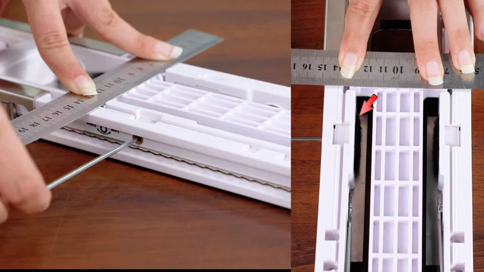
The hex key enters the first side hole. The close-up points to the corresponding black pad.
Turn the screw on the opposite side and watch the second pad.
The dashed lines mark the inward-facing pad edges at the 5 cm example setting.

7. Pull the white handle to open the lower plate

Watch at 02:22

Find the white release handle underneath the front of the support. Pull and hold it so the spring-loaded lower plate opens away from the main support. Keep it open as you bring the unit to the cylinder arm.
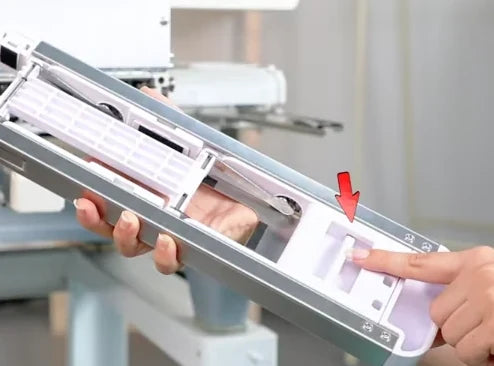
The arrow identifies the white release handle under the front end.
Pulling the handle opens the lower plate and creates a gap for the cylinder arm.

8. Slide the support fully on and release

Watch at 02:33

Guide the open support straight onto the cylinder arm and slide it all the way in. Release the white handle so the lower plate springs back against the arm. Gently wiggle the front to check how firmly it sits.

Slide the support onto the arm while holding the lower plate open.
After release, the lower plate springs up under the cylinder arm.
Grip the front end and check for movement with a gentle wiggle.

9. Fine-tune both sides if the support is loose

Watch at 02:49

If there is play after mounting, tighten the matching left and right screws by the same number of turns to keep the support centered. The video illustrates two turns per side first, then one more turn per side if needed. It shows the white end-block screws and the extension-slide side screws. Recheck the fit between adjustments.
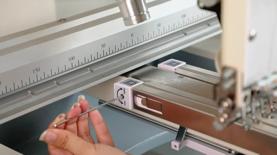
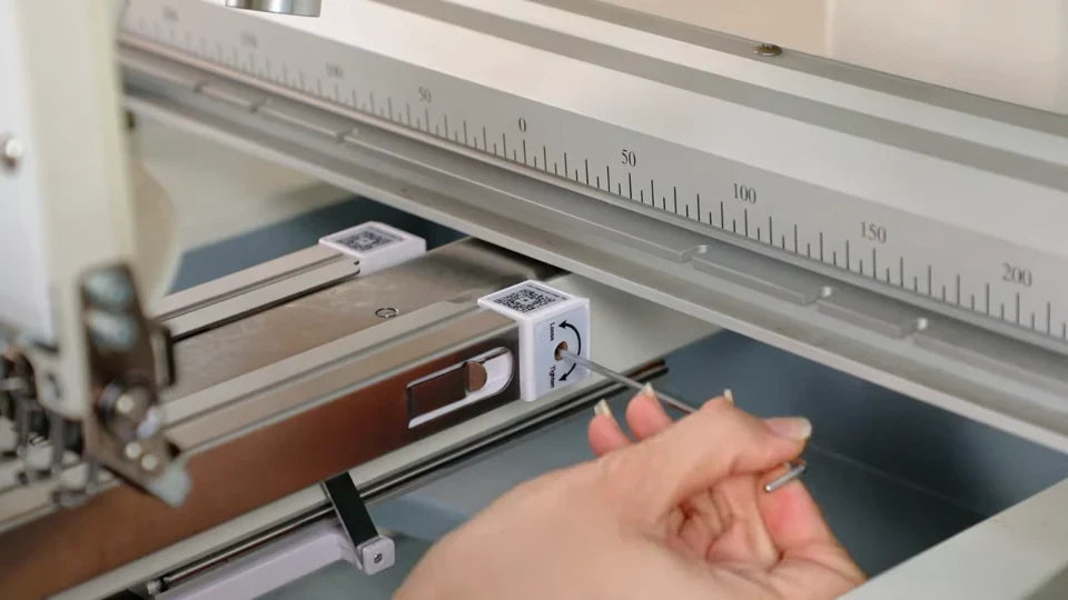
The installed support still gives access to the end-block adjustment screw.
Match the number of turns on the opposite end block.
The side screw on the extension slide is also shown during the fine adjustment.

10. Confirm a secure fit and smooth release

Watch at 03:08

Gently wiggle the mounted support again. It should sit securely on the cylinder arm, and it should slide on and off smoothly when you hold the release handle open.
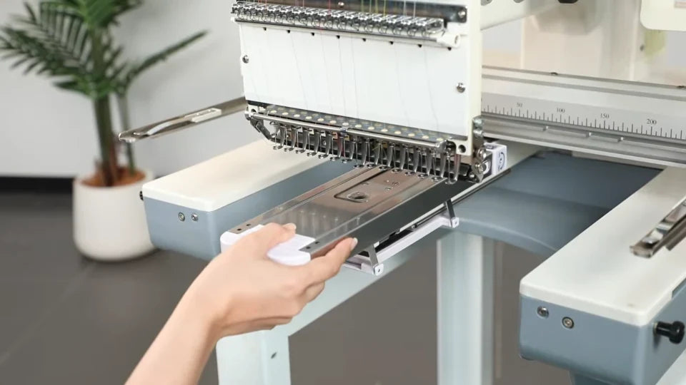
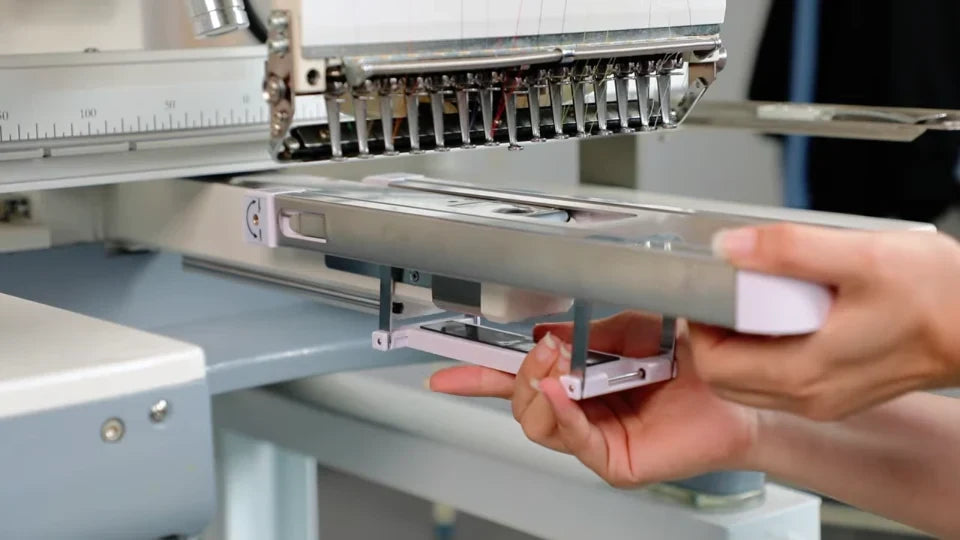
The final wiggle tests whether the installed support still has play.
With the lower plate open, the support can slide along the cylinder arm.

11. Extend the slide to support a larger hoop

Watch at 03:17

Pull the front section out to reach farther under a larger hoop. Fit the hoop to the machine arms. Watch the hoop travel over the extended support in the demonstration and check that the support sits beneath the hoop and fabric.
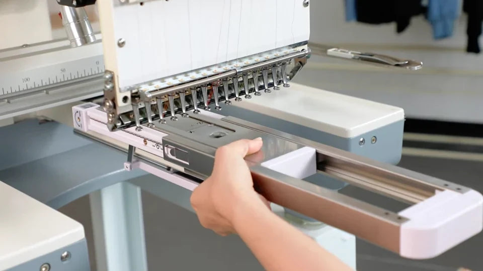
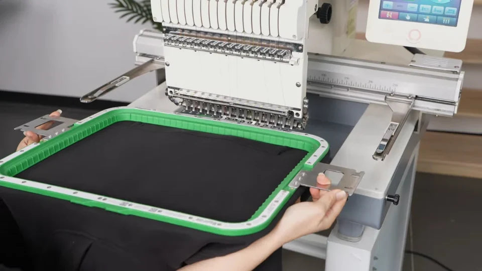
The front section extends beyond the end of the cylinder arm.
Fit the larger hoop to the machine’s two hoop arms.
The exposed slide shows how far the support reaches beneath the hoop.

12. Remove HoopSteady

Watch at 03:33

With the hoop off as shown, support the front of HoopSteady with one hand. Pull and hold the white handle with the other to lower the bottom plate. Slide the whole unit straight off the cylinder arm.

Reach under the front end for the white release handle.
Hold the plate open as you pull the support away from the cylinder arm.
The cylinder arm is clear once the support is removed.