Add a New Hoop Size on the ST-1501

Overview
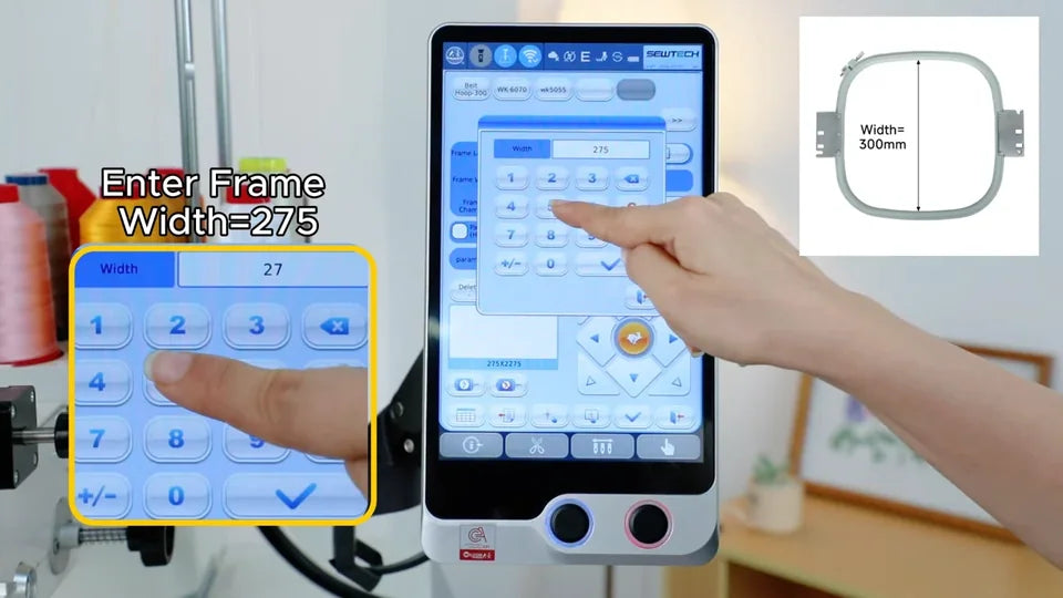
Add a hoop profile on the ST-1501 by measuring the physical opening, entering a working area with clearance, and saving the laser-aligned center. The demo uses a 300 × 300 mm hoop and verifies the new profile by selecting it and running the automatic Center move.
Step-by-step guide
1. Clamp stabilizer in the new hoop
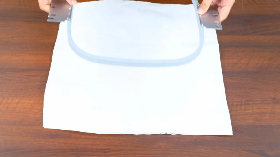
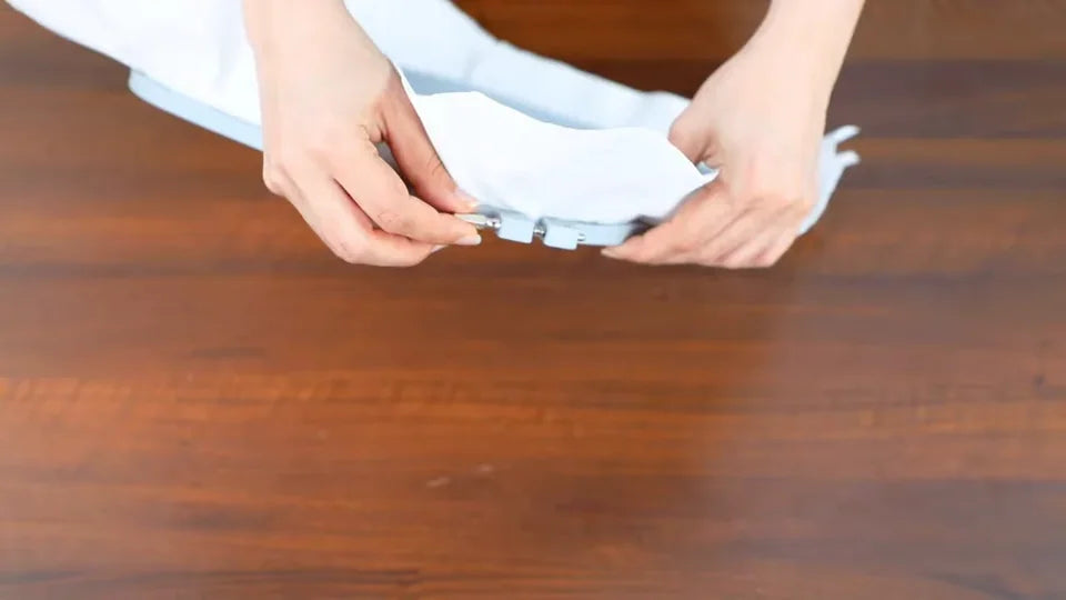
Watch at 00:10Lay a piece of stabilizer across the lower ring, seat the upper frame over it, and tighten the hoop so the sheet stays flat. Have a ruler and a washable fabric pen ready to mark the center.
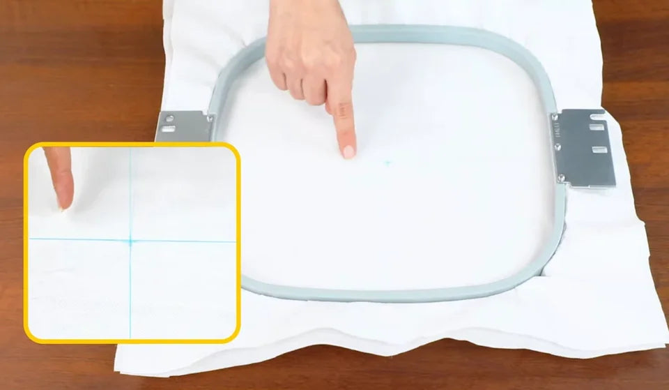
2. Measure the hoop and mark its physical center
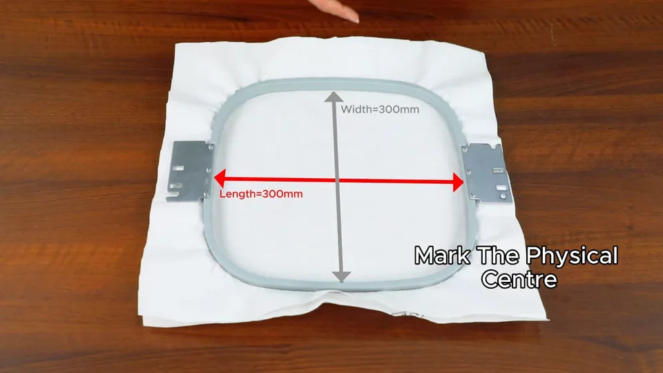
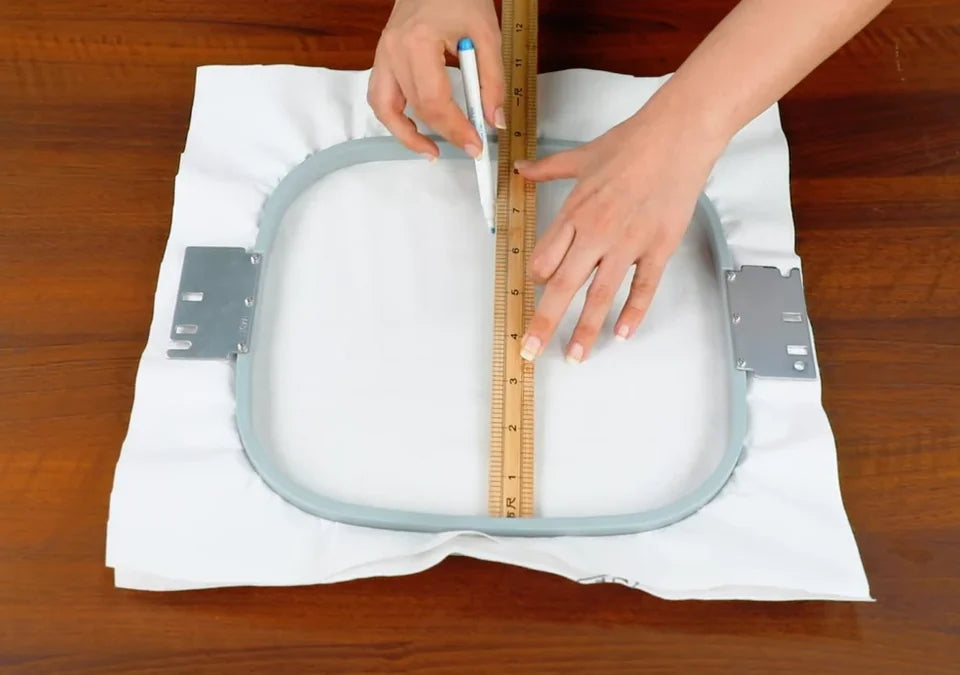
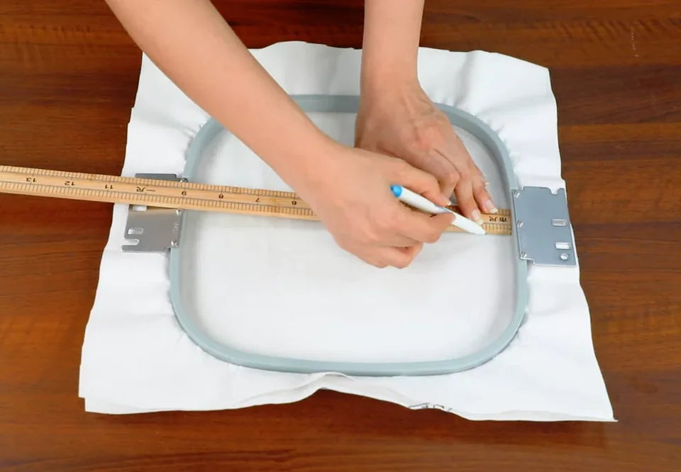
Watch at 00:18Measure the opening in both directions with the ruler. Use the washable pen to draw a vertical midline and then a horizontal midline on the stabilizer. The intersection marks the hoop’s physical center. The opening shown measures 300 × 300 mm.
3. Check the laser against the needle plate
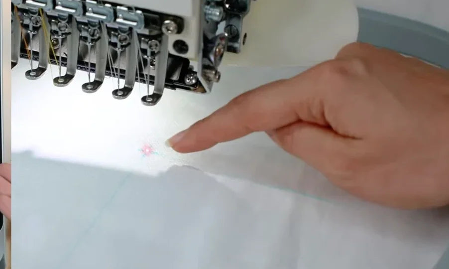
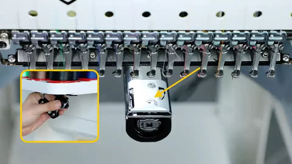
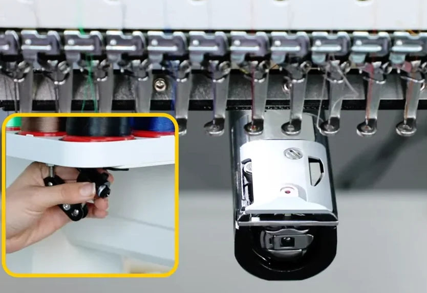
Watch at 00:47Before mounting the hoop, locate the center reference on the needle plate beneath the needle bank. Check that the laser dot lands on that reference. The video shows the laser unit in the inset beside the needle plate.
4. Mount the hoop on both arms
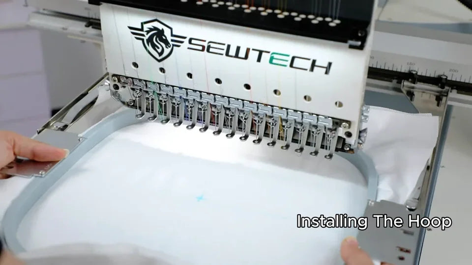
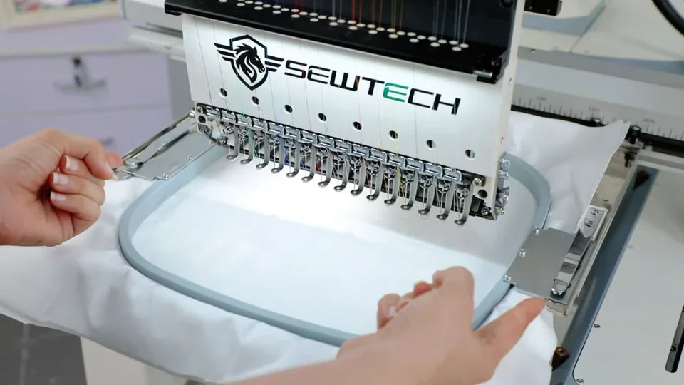
Watch at 01:01Slide the hoop’s two side brackets into the machine arms beneath the needle head. Check both sides for secure seating and gently check that the hoop does not wobble.
5. Switch to needle 1
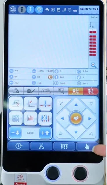
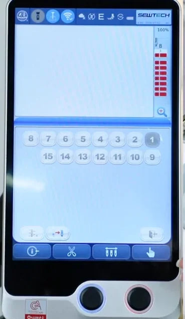
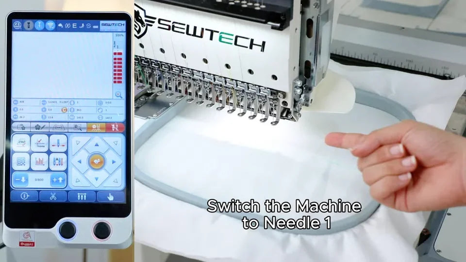
Watch at 01:14Tap the hand icon at the bottom right of the control screen to open manual needle selection. Select 1 at the right end of the top row before setting the hoop position. Watch the head shift to bring the selected needle into position.
6. Open the hoop list and select None Frame
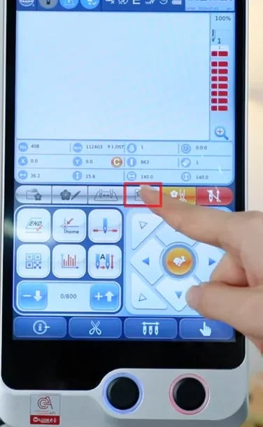
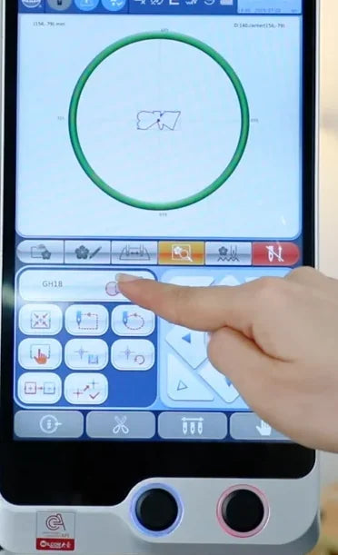
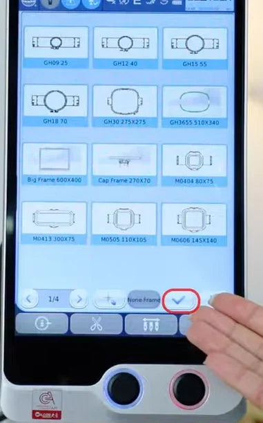
Watch at 01:24Open the frame tab, fourth in the control row beneath the preview. Tap the current frame label to open the list. At the bottom, tap None Frame (called No Frame in the video) and then the blue checkmark. The demo controller already lists a GH30 275 × 275 preset, which the presenter points out before creating the example entry.
7. Open frame parameters and add a blank entry
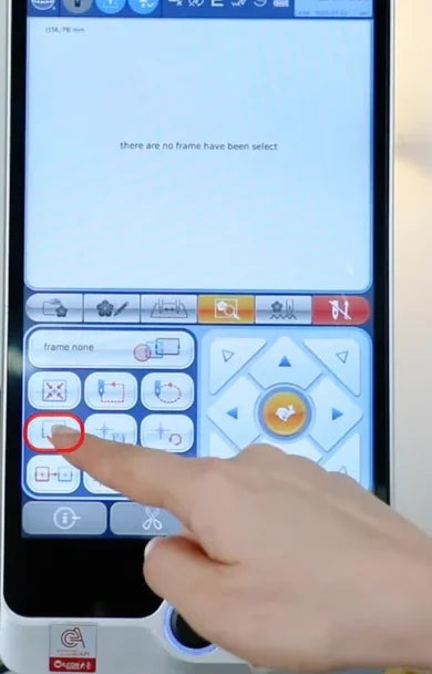
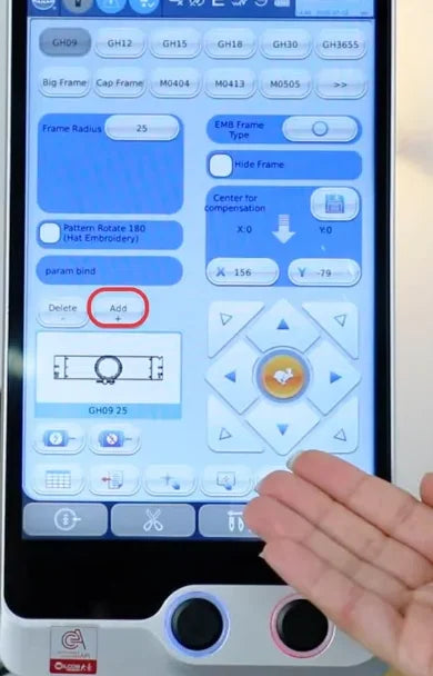
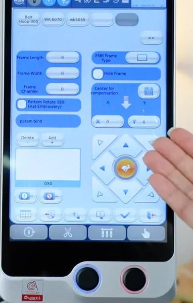
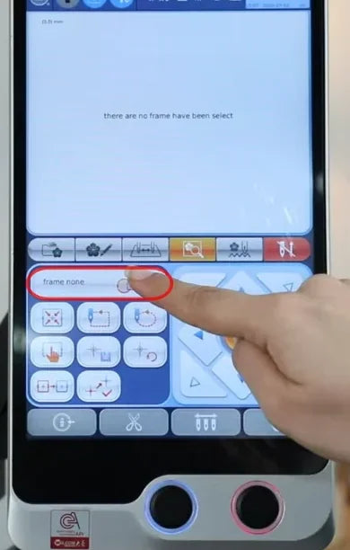
Watch at 01:39With the frame field showing frame none, tap the first small button in the second row below it to open frame parameters. In the parameter screen, tap Add beside Delete. A blank entry opens with the size fields at zero and a 0 × 0 preview.
8. Enter the usable length and width
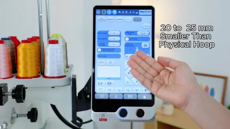
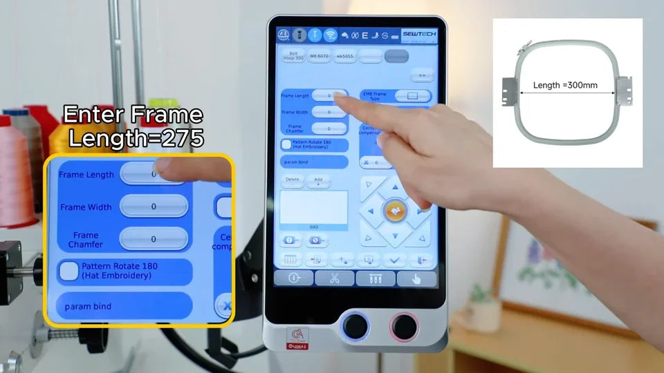
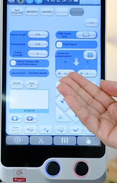
Watch at 01:49The tutorial recommends entering dimensions 20 to 25 mm smaller than the measured hoop in each direction to leave needle clearance. For this 300 × 300 mm example, tap Frame Length and enter 275 on the keypad, then confirm it. Do the same in Frame Width. The entry preview reads 275 × 275 after both values are accepted.
9. Set the chamfer or use the radius field for a round hoop
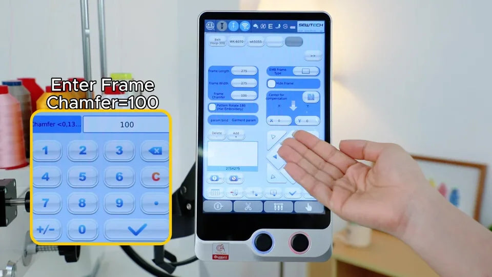
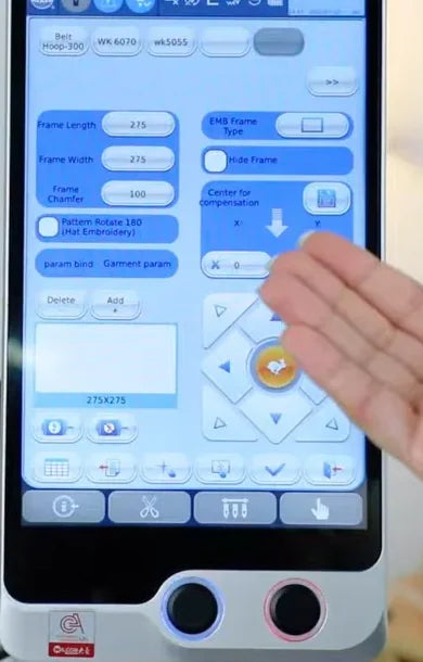
Watch at 02:19Tap Frame Chamfer, enter 100 on the keypad for the rounded-corner hoop shown, and tap the keypad checkmark. Use the value for your own hoop shape. For a circular hoop, the tutorial specifies entering only the radius in the circular frame’s Frame Radius field.
10. Return the frame to its origin
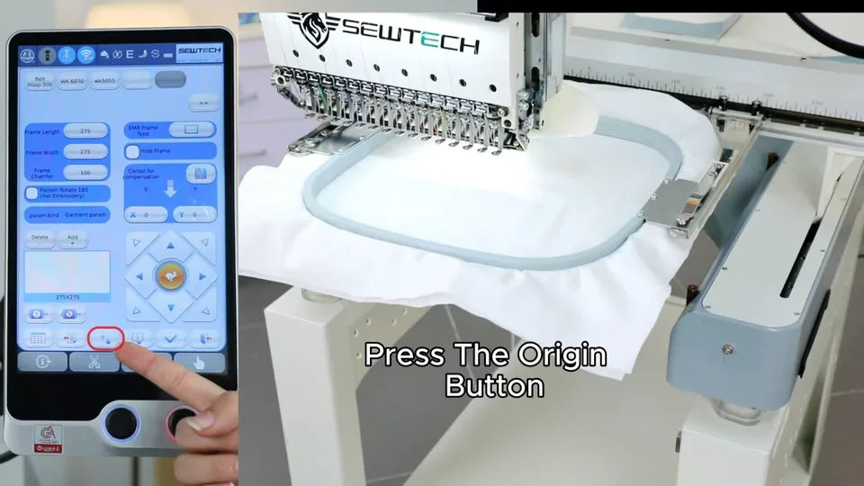
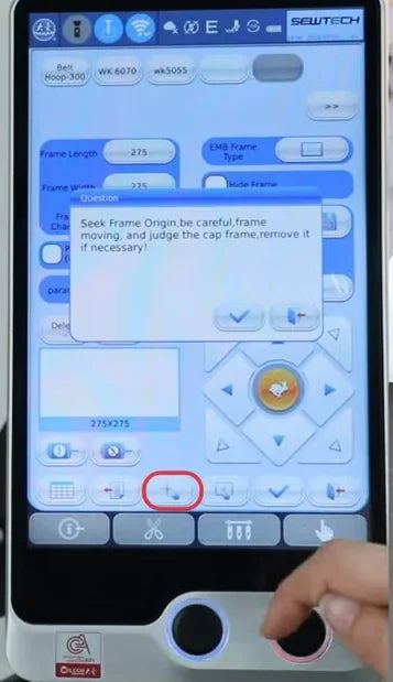
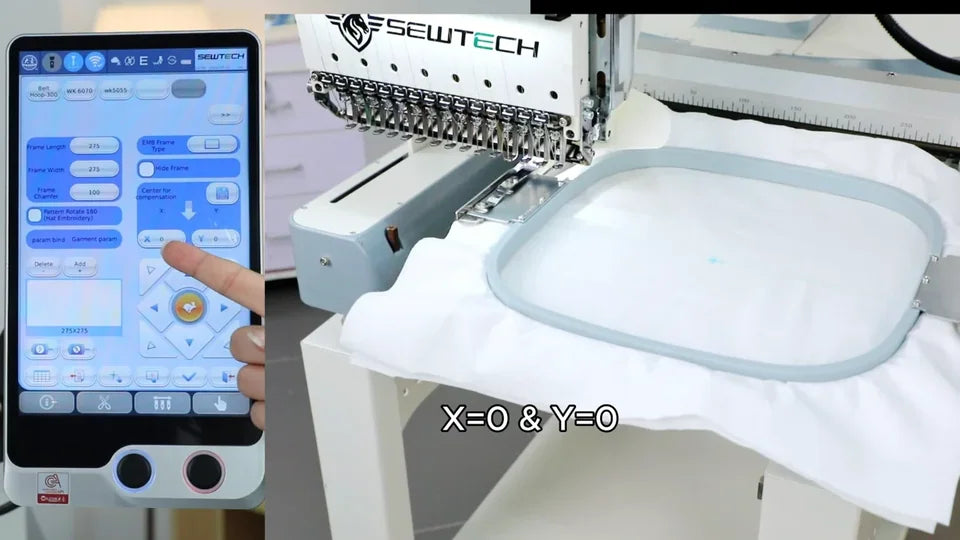
Watch at 02:33Tap the Origin button in the bottom row of the parameter panel, as circled in the video. The Seek Frame Origin prompt warns that the frame will move and may require cap frame removal. Clear the travel path, remove a cap frame if needed, and tap the prompt’s checkmark. After movement stops, confirm the live X and Y readouts are both 0.
11. Jog the frame until the laser meets the crosshair
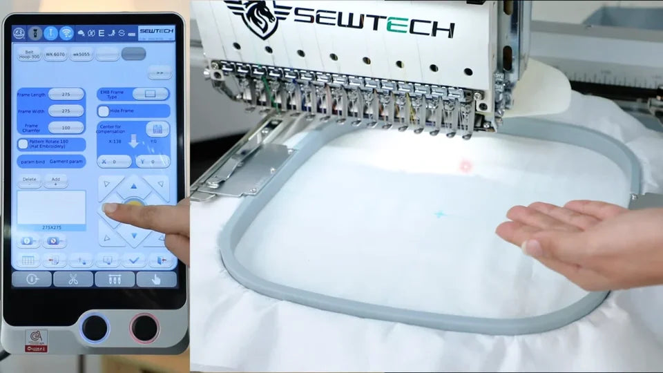
Watch at 02:42Use the arrow pad on the right of the parameter screen. The left and right arrows move along X; up and down move along Y. Watch the red laser dot and the crosshair on the stabilizer. Move the frame in both axes as needed until the dot sits on the intersection.
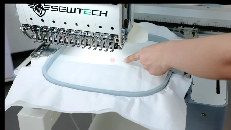
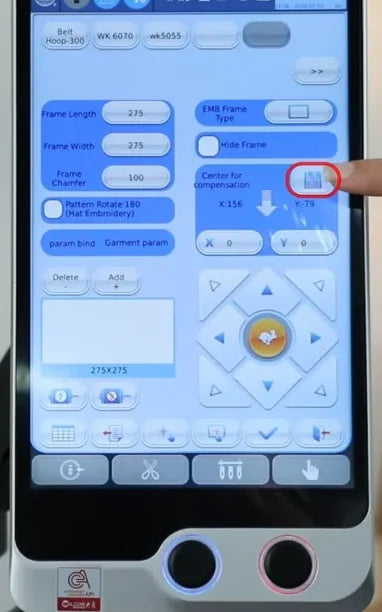
12. Save the aligned X and Y and confirm the entry
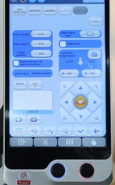
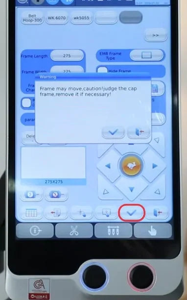
Watch at 03:08When the laser is on the crosshair, check the current X and Y under Center for compensation. Tap the disk icon in that panel to copy the current coordinates into the saved fields. Use the values measured on your machine. Tap the parameter panel’s bottom checkmark, then confirm the frame movement warning with its own checkmark after checking clearance.
13. Reopen the hoop list and select the new entry
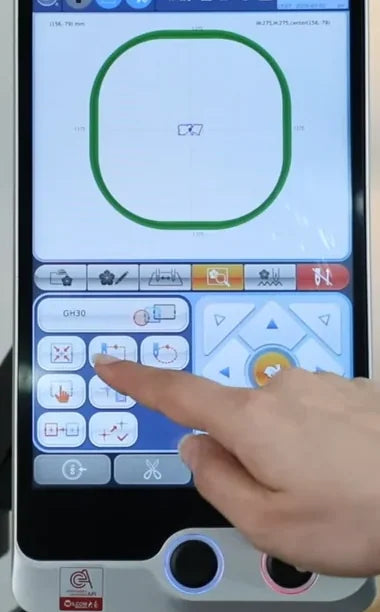
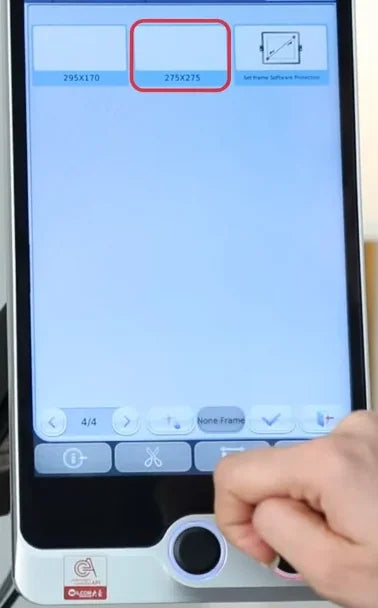
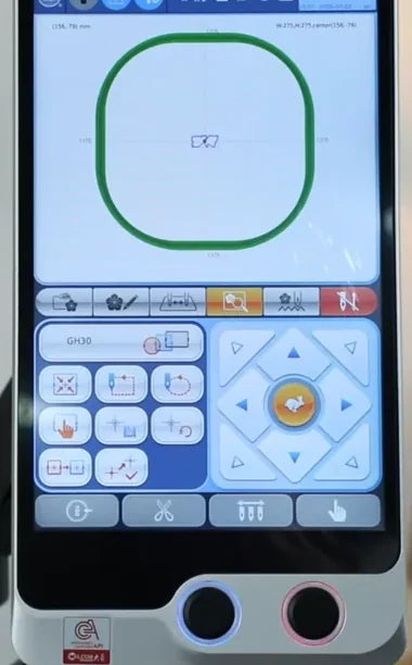
Watch at 03:19From the frame tab, tap the frame none field again. Page through the hoop list to find the new size. The video shows the 275 × 275 entry on page 4/4. Highlight it and tap the bottom checkmark. The preview now shows a green rounded hoop outline.
14. Run the Center move and verify the laser
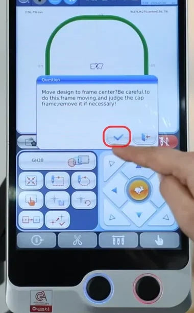
Watch at 03:26In the small button grid under the selected frame, tap the middle button in the top row to move the design to the frame center. Check clearance and confirm the on-screen prompt. After the hoop moves automatically and stops, the laser should land on the same pen crosshair. Before stitching, check that the intended design fits within the usable hoop area.