SEWTECHSupport Center 简体中文

Set Magnetic Hoop Parameters on the ST-1501

Applies to ST-1501

Watch on YouTube ↗

Overview

Measure and mark the physical center of a magnetic hoop, record a stitch area with clearance, and save and test the hoop’s center on the ST-1501. Have the hoop, a piece of stabilizer, a ruler and a washable fabric pen ready.

Step-by-step guide

1. Clamp stabilizer in the magnetic hoop

Watch at 00:10

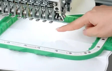
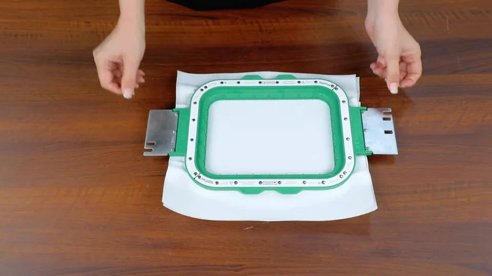
Lay the lower hoop flat on the table and spread a piece of stabilizer over the opening. Seat the magnetic top frame over it. Check that the stabilizer lies flat, is held all the way around and gives you room to mark the center.
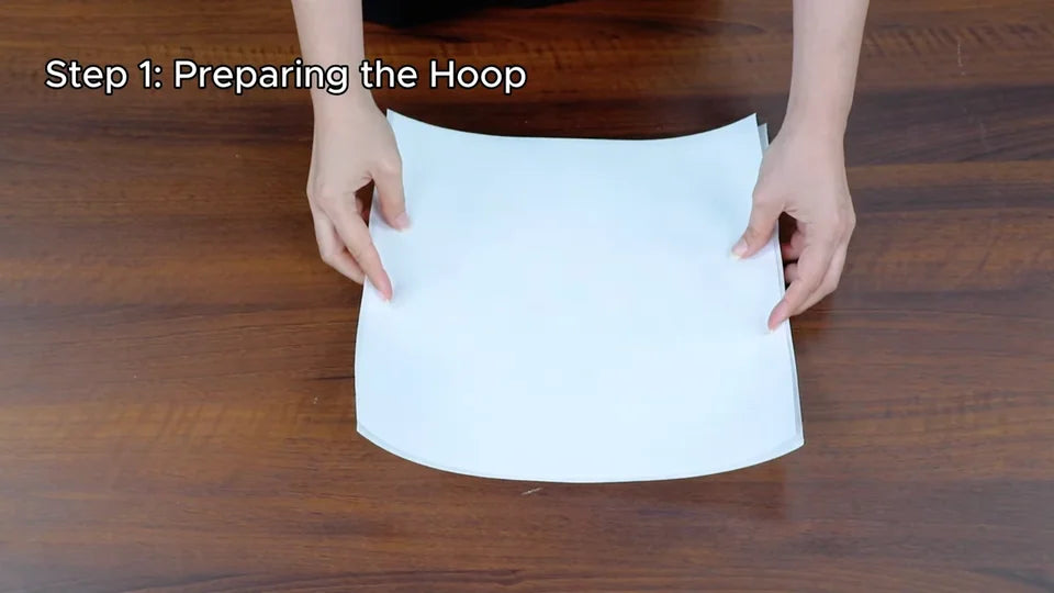
Cover the lower frame opening with stabilizer.
The magnetic top frame holds the stabilizer flat across the opening.

2. Measure and mark the physical center

Watch at 00:17

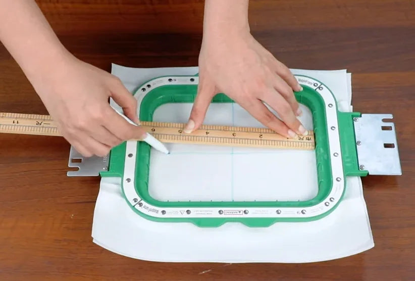
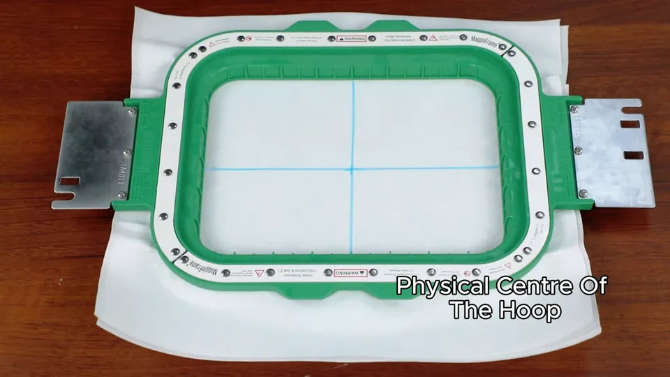
Measure the horizontal length and vertical width of the hoop opening with a ruler. Find the midpoint in each direction. With a washable fabric pen, draw a vertical midline and then a horizontal midline on the stabilizer. The intersection is the mark you will align with the laser.
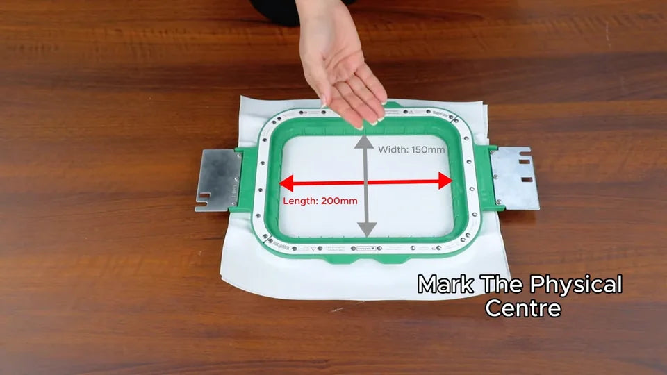
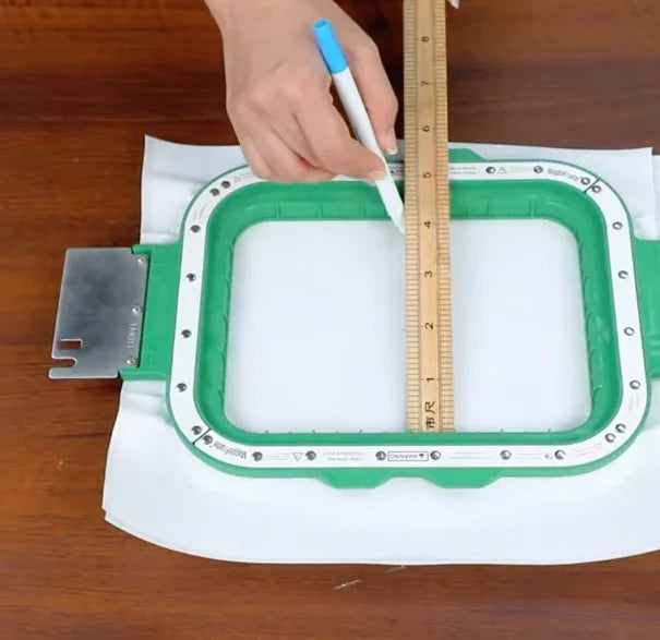
The overlay shows the two opening dimensions measured across the frame.
Use the ruler as a straightedge for the vertical midline.
Turn the ruler to draw the horizontal midline.
The crossing on the stabilizer marks the physical center.

3. Check the laser at the needle plate

Watch at 00:43

With the hoop still off the machine, check that the red laser dot falls on the center reference on the needle plate. Get those two points aligned before using the laser to locate the hoop center.
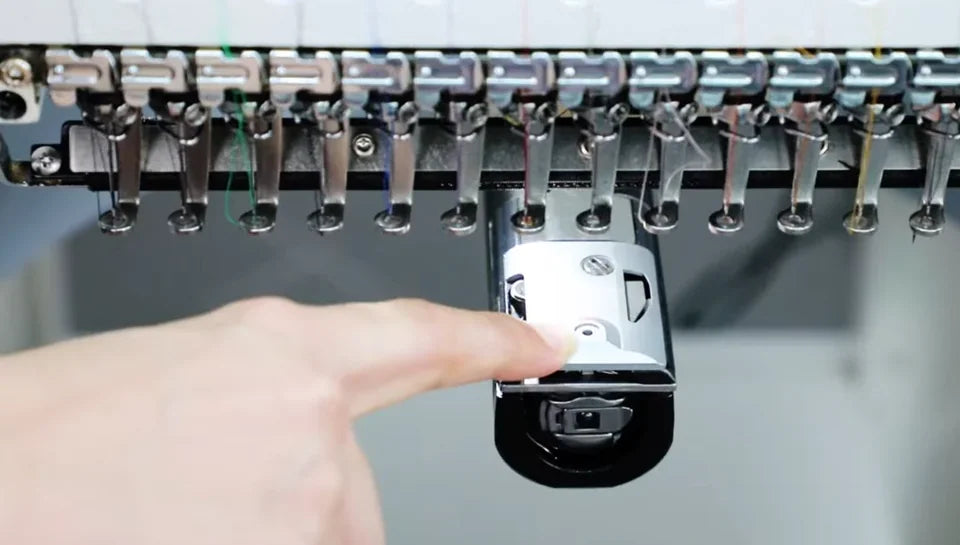
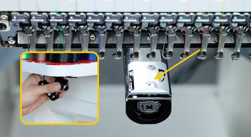
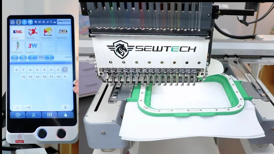
The presenter indicates the center reference on the needle plate beneath the head.
The arrow indicates the reference point. The inset shows the laser adjustment location.

4. Mount the marked hoop securely

Watch at 00:56

Slide the hoop onto the machine’s two hoop arms with the marked stabilizer facing up. Seat both side brackets fully. Gently check that both sides are secure and the hoop does not wobble.
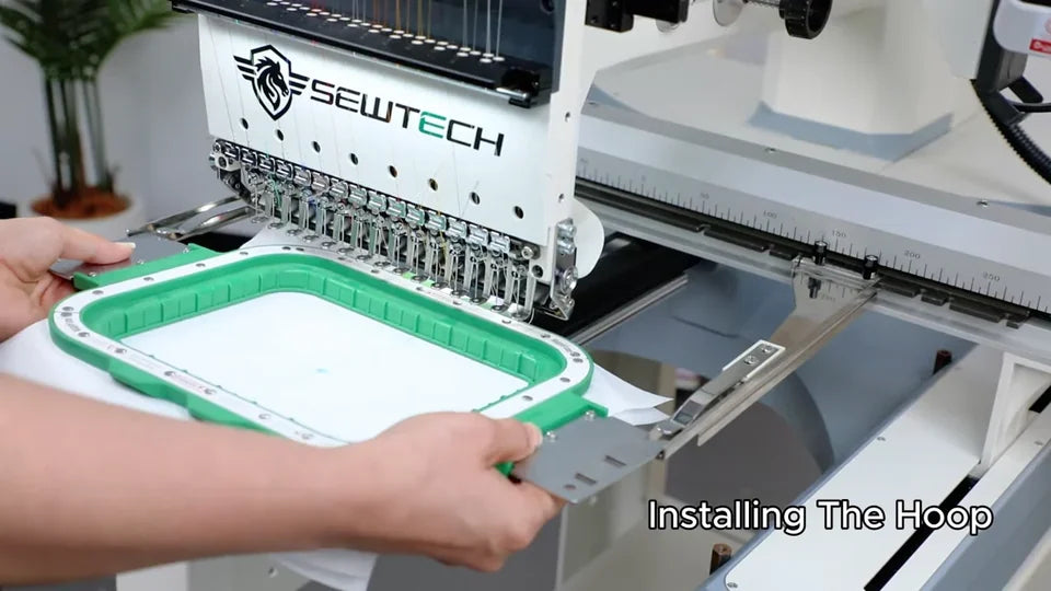
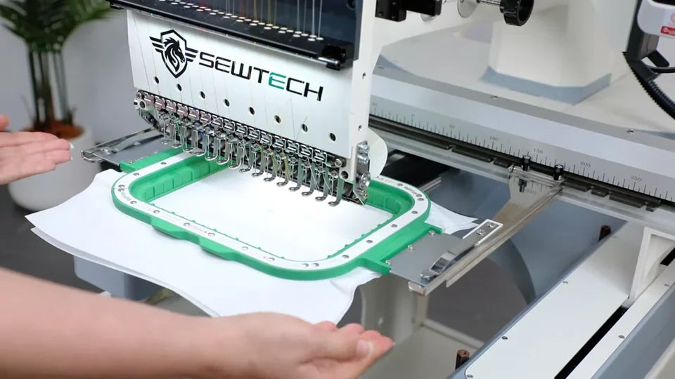
The two side brackets approach the hoop arms with the marked side facing up.
With both brackets seated, check the installed hoop for movement at the mounts.

5. Select needle 1

Watch at 01:04

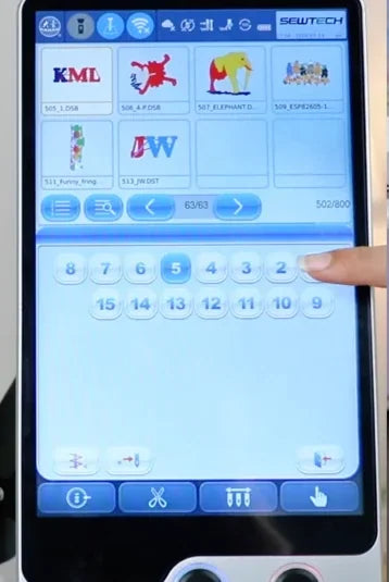
Tap the three-needle icon on the bottom bar to open the manual needle selector. Tap 1 at the right end of the upper row. Let the head shift to needle 1 before setting the frame position. The 1 button becomes highlighted.
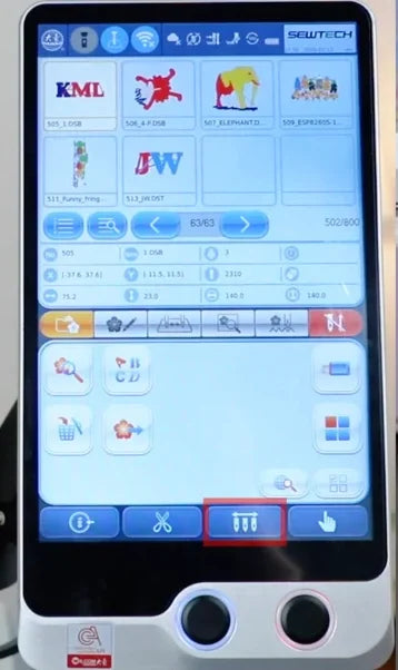
The red box identifies the three-needle button on the bottom bar.
Needle 1 is at the right end of the upper row. Needle 5 is highlighted before the switch.
The highlighted 1 confirms the needle change.

6. Open frame selection and choose None Frame

Watch at 01:12

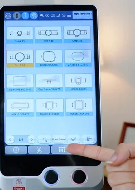
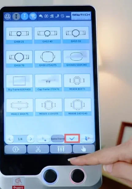
On the touchscreen, open the frame controls using the highlighted fourth tab in the middle row. Tap the current-frame field to bring up the hoop list. At the bottom of the list, select None Frame and tap the blue checkmark. The preview then reports that no frame is selected. The example hoop already appears in the presenter’s machine history, so your existing list may differ.
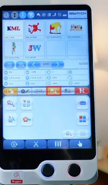
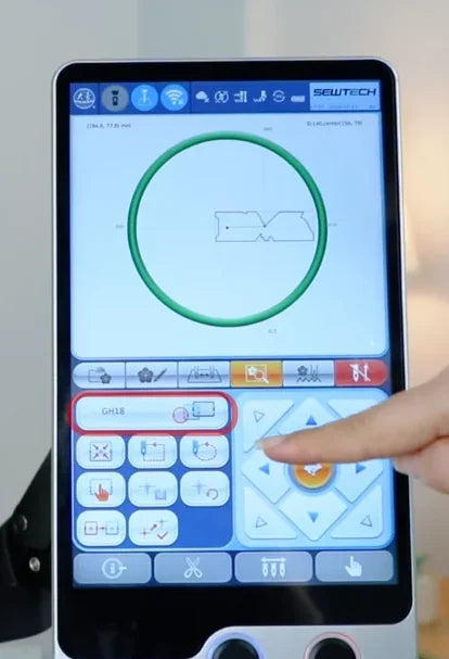
The red box marks the frame-controls tab on the middle toolbar.
The red box marks the current-frame field that opens the hoop list.
The bottom row of the list shows None Frame beside the blue checkmark.
The boxed checkmark confirms the None Frame selection.

7. Open frame parameters and add an entry

Watch at 01:32

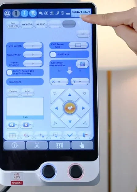
Back on the frame-controls page, tap the left button in the second row of the small control grid below the current-frame field. On the parameter page, tap Add below the dimension fields, beside Delete. The video shows a new slot with blank or zeroed dimensions ready for entry.
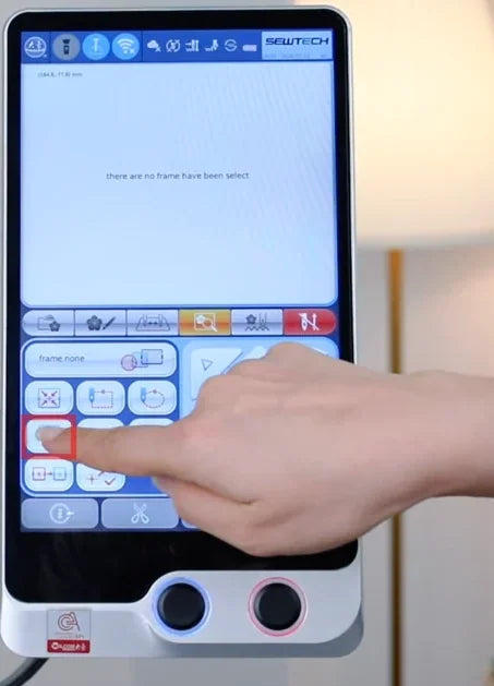
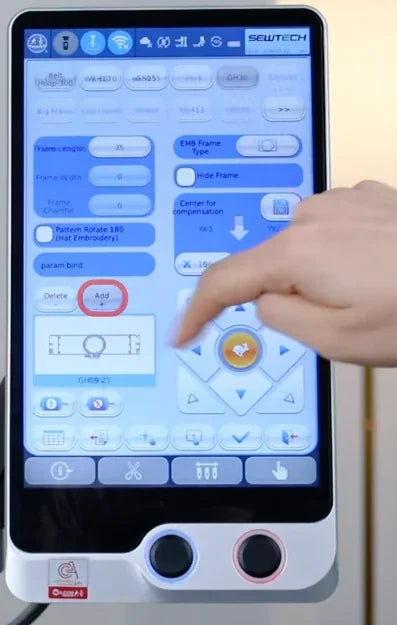
The red box shows the frame-parameter button in the small grid below the frame field.
Add is beside Delete, below the frame dimension fields.
The new slot shows zero values for the frame length, width and chamfer.

8. Enter the safe stitch-area dimensions

Watch at 01:41

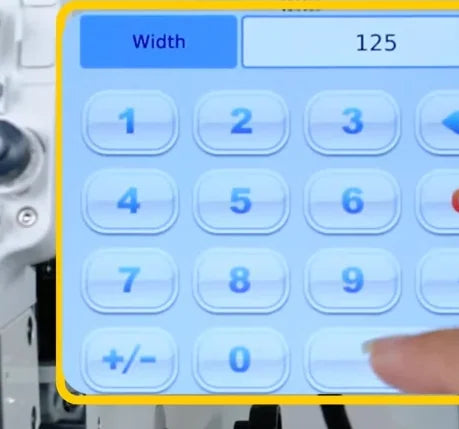
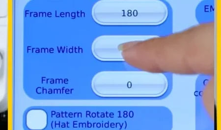
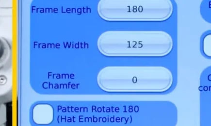
Use the opening you measured to size the stitch area. The video recommends making each overall dimension 20–25 mm smaller to leave clearance from the frame. In the 200 × 150 mm example, open Frame Length, enter 180, and accept with the keypad checkmark. Do the same for Frame Width with 125. Calculate the entries from your own hoop’s measurements.
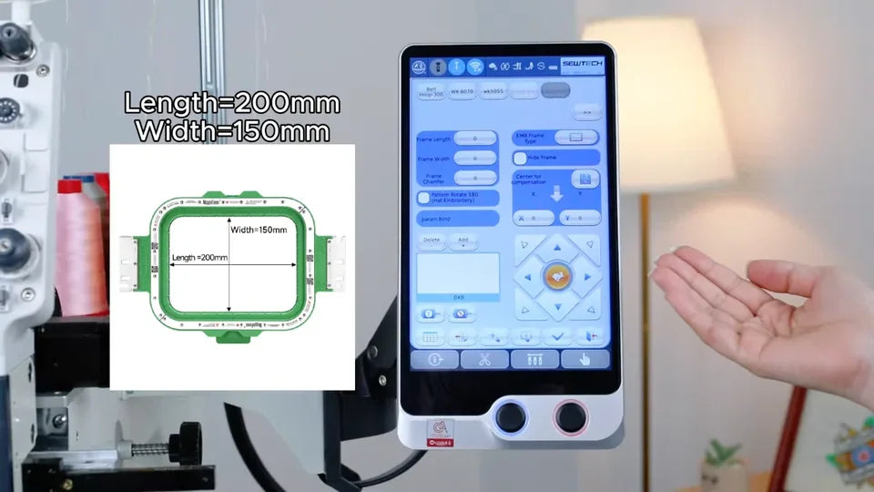
The measured opening in the example is 200 mm long and 150 mm wide.
Frame Length reads 180 as the presenter opens Frame Width.
The Width keypad shows 125 before the value is confirmed.

9. Set the frame chamfer

Watch at 02:12

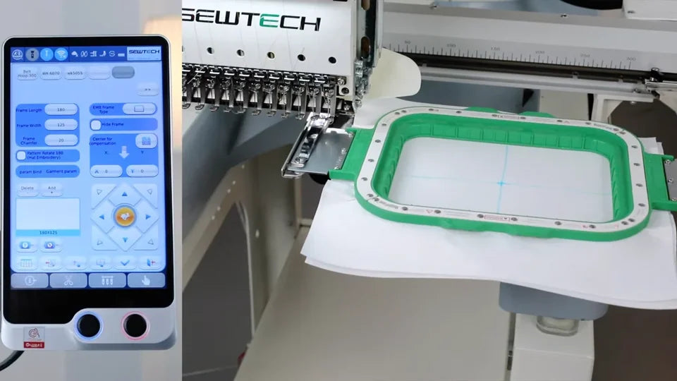
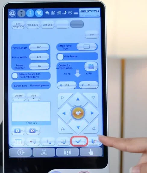
Tap Frame Chamfer under the width field, enter the value for this hoop’s corners and confirm it on the numeric keypad. The demonstration uses 20 for the example hoop. Before proceeding, check that the panel shows all three intended entries.
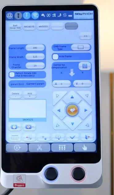
The inset identifies Frame Chamfer beneath Frame Length and Frame Width.
The example fields now read 180 for length, 125 for width and 20 for chamfer.

10. Send the hoop to the frame origin

Watch at 02:22

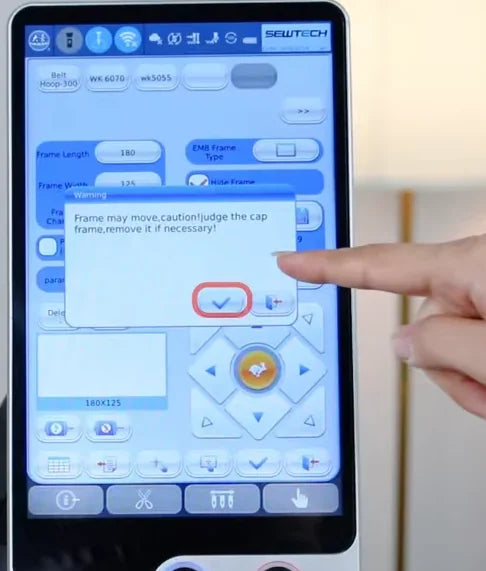
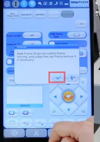
Tap the frame-origin control in the lower toolbar of the parameter page, third button from the left. When Seek Frame Origin appears, keep the hoop’s travel path clear and tap the dialog checkmark. Watch the carriage move and wait for it to stop at its starting position.
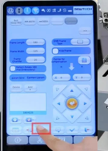
The video boxes the origin button, third from the left on the lower toolbar.
The Seek Frame Origin prompt warns that the frame will move and shows the confirmation checkmark.
After the return, the hoop is at its starting position for manual adjustment.

11. Jog the hoop until the laser meets the mark

Watch at 02:30

Use the direction arrows on the right of the frame-parameter screen to move the mounted hoop. Watch the red dot against the two pen lines. Stop when the dot sits on their intersection, then read the current X and Y above the offset fields.
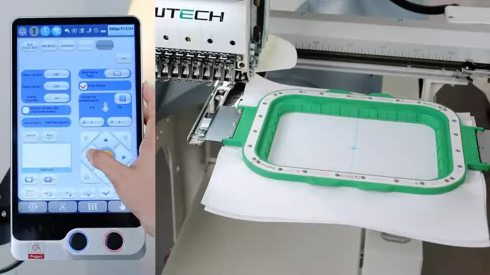
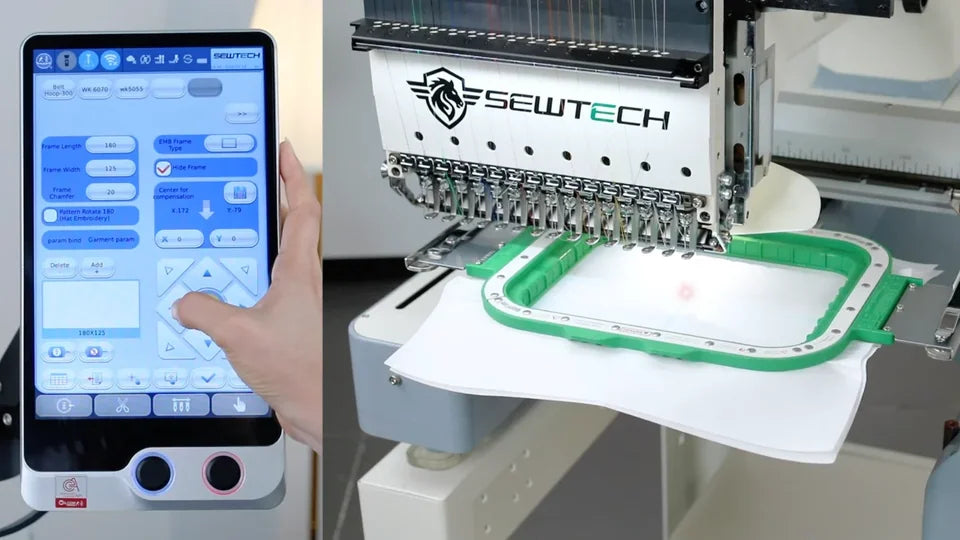
The direction pad jogs the hoop from the origin position.
Watch the laser dot and the pen lines while moving the hoop.
The presenter points to the laser at the marked crossing before saving.

12. Save the center offsets and confirm

Watch at 02:47

In Center for compensation, read the live X and Y while the dot still sits on the mark. Tap the disk icon to write the live readings into the X and Y fields below. Check that the stored values match the live readings. In the video they are X 178 and Y −79. Tap the parameter page checkmark and then the dialog checkmark after checking the movement path.
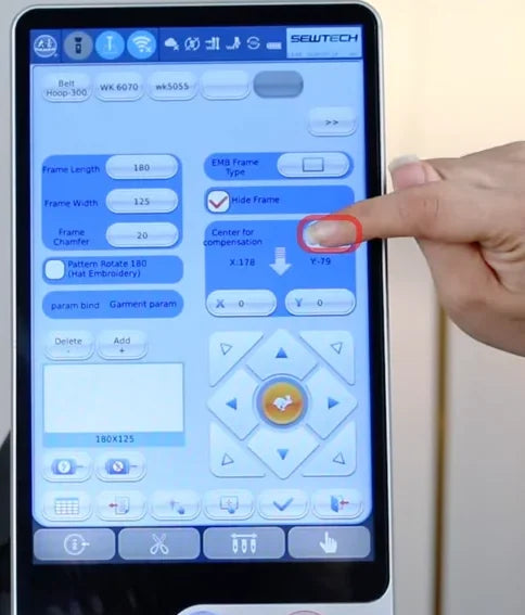
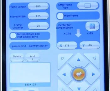
The disk icon saves the live center readings shown above the X/Y fields.
The lower fields now match the live example readings of X 178 and Y −79.
The bottom checkmark confirms the frame parameters.
The controller asks for confirmation because the frame may move.

13. Reselect the saved hoop

Watch at 02:59

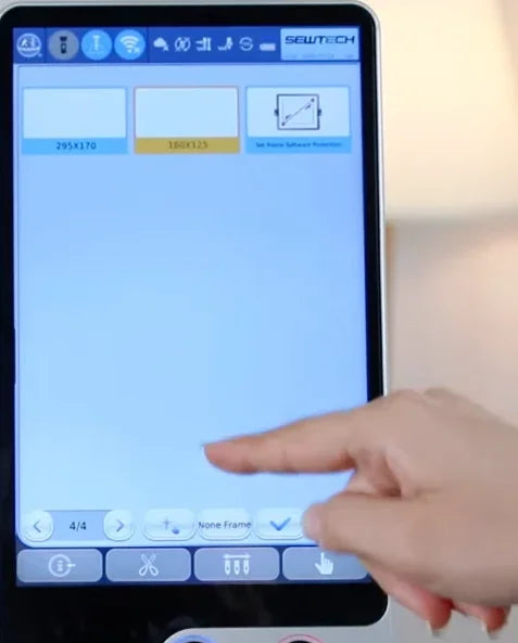
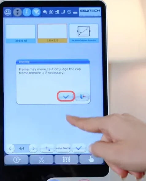
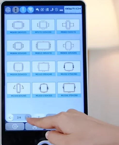
Open the hoop list again from the current-frame field. Use the bottom next-page arrow to find the saved size. The example 180 × 125 tile is on page 4/4. Tap it and check that its label turns yellow, then tap the blue checkmark. Confirm the movement warning when the path is clear.
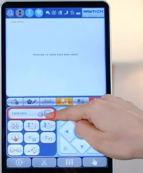
Tap the current-frame field to reopen the hoop list.
Use the arrow beside the page number at the bottom to advance through the list.
The saved 180 × 125 tile is highlighted yellow on page 4/4.
A frame-movement warning appears after the selection is confirmed.

14. Run the center command and verify the laser

Watch at 03:09

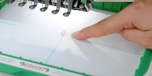
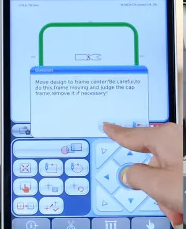
On the frame-controls screen, tap the center command at the upper left of the small button grid. Confirm the Move design to frame center? prompt and let the hoop come to a stop. Check the stabilizer in the hoop. The red dot should fall on the pen-line intersection again. That alignment is the video’s final check that the saved center works. Before stitching, check that the design fits the configured area and that the frame clears the needle throughout the intended movement.
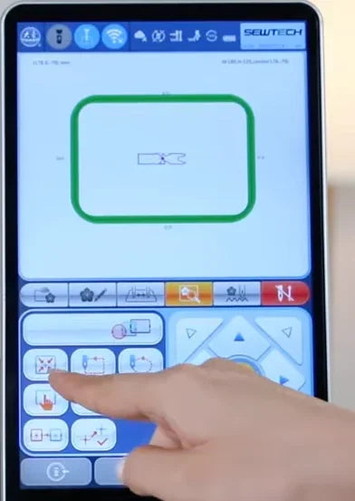
The green outline shows the selected hoop. The presenter taps the center control in the small grid.
Confirm the center-movement prompt, then wait for the hoop to stop.
The red laser dot lands on the intersection of the blue pen lines.