SEWTECHSupport Center 简体中文

Install the Flat Table on the ST-1501

Applies to ST-1501

Watch on YouTube ↗

Overview

Install the flat table on the ST-1501 in two stages. First fasten the support brackets to the tabletop through its eight holes. Then slide the assembly onto the machine, align the four machine mounting points, and tighten the four mounting screws.

Step-by-step guide

1. Lay out the tabletop, brackets and screws

Watch at 00:11

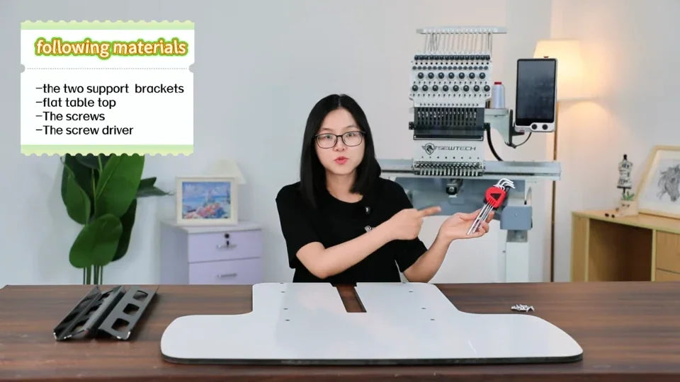
Set out the slotted tabletop, the two black support brackets, the bracket screws and the four machine mounting screws. Have a tool that fits the screw heads ready. Claire uses L-shaped hex keys in the close-ups.
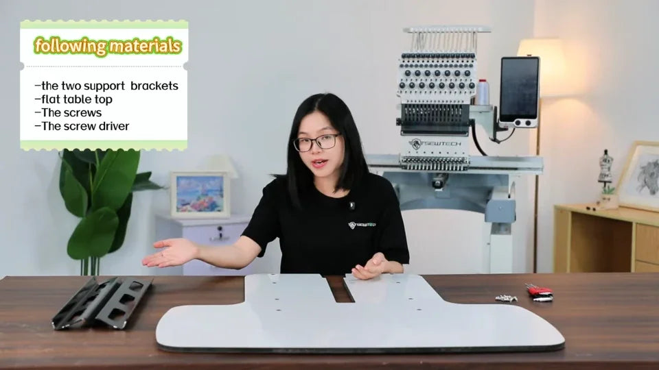
Set the two black brackets beside the slotted tabletop.
The parts shot shows the fasteners and L-shaped hex keys.

2. Find the eight tabletop holes

Watch at 00:31

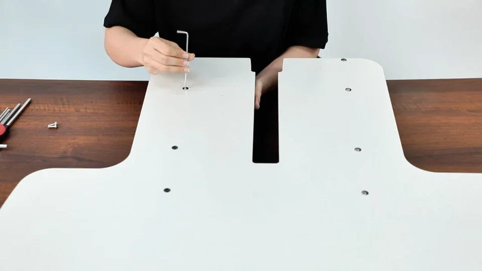
Lay the tabletop flat with the working face up. Locate the two rows of mounting holes beside the center slot. The video circles four on each side.
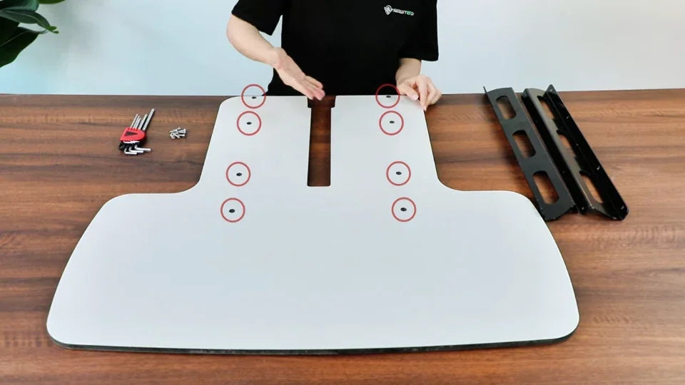
The eight red circles mark four bracket screw holes on each side of the center slot.

3. Match each bracket to its row of holes

Watch at 00:37

Use the overhead layout to see which bracket goes on each side of the slot. Compare the holes in each bracket with the row on that side before placing the brackets under the tabletop.
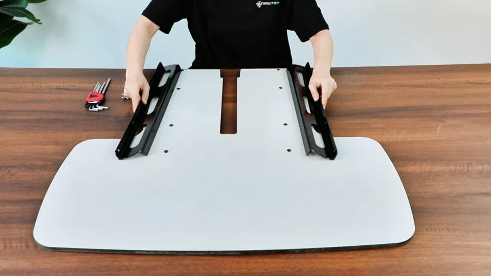
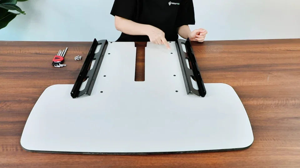
Compare the two brackets against the two rows alongside the slot.
Use the row beside the slot to line up the second bracket.

4. Fit the brackets underneath with the flanges facing out

Watch at 00:54

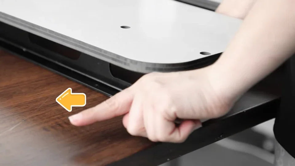
Lift the slotted end enough to position a bracket beneath each hole row. Face the lower bent flange of each bracket outward, away from the center slot, as shown by the arrow. Keep the bracket holes under the corresponding tabletop holes.
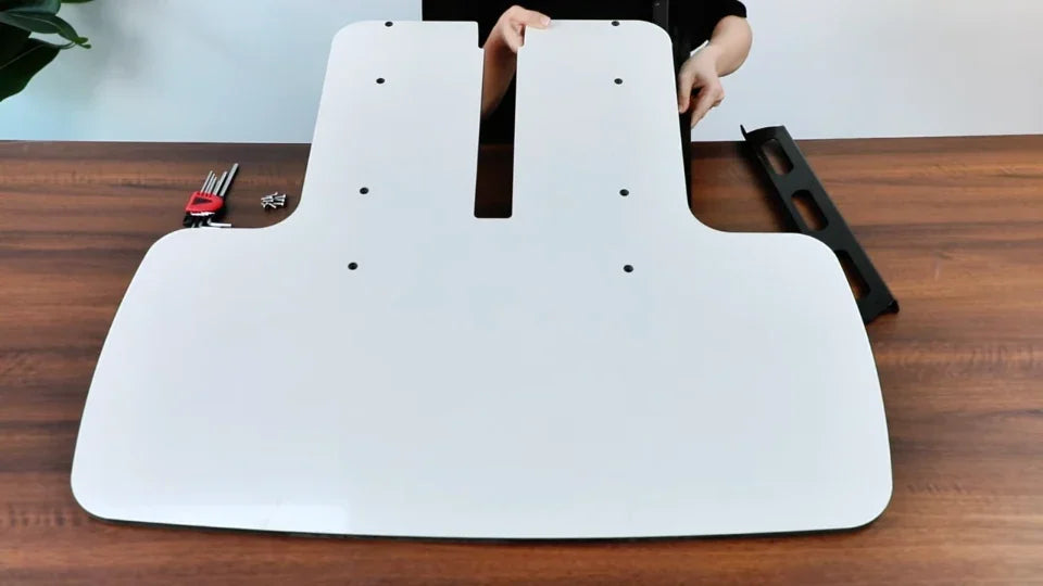
The presenter lifts the slotted end and moves a bracket underneath.
The arrow shows the outward direction for the black bracket flange.

5. Start the bracket screws from above

Watch at 01:06

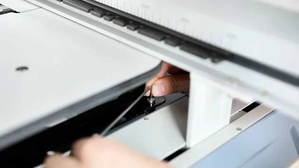
Insert the screws down through the tabletop into the brackets. Turn each screw just enough to catch the threads with the hex key. Leave them slightly loose while you start all eight across the two rows.
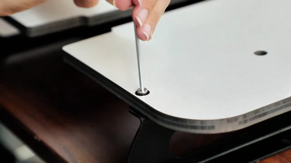
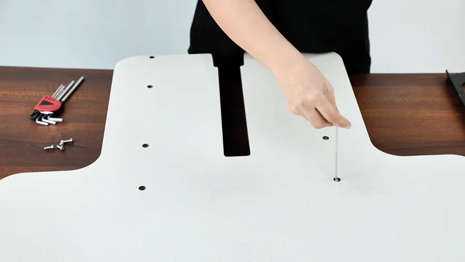
The hex key engages a screw through a hole in the top face.
Continue down the first row before moving to the other side.
Start the screws in the other bracket through the second row.

6. Tighten both rows after every screw is started

Watch at 01:34

Check that each screw has entered its bracket and both brackets are aligned. Then go back through both rows and tighten the screws with the hex key before lifting the assembly to the machine.
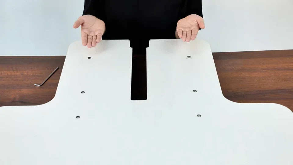
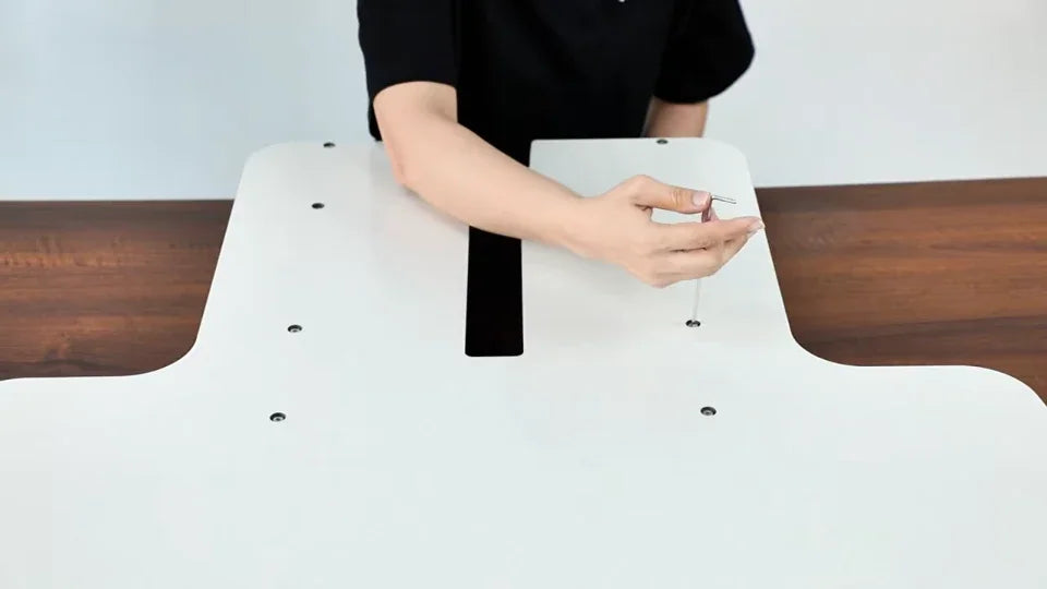
Check the fasteners along both sides of the slot before final tightening.
Return to the fasteners with the hex key for final tightening.

7. Locate the four mounting points on the machine

Watch at 01:44

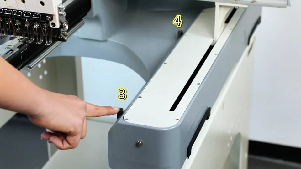
With the machine stopped, look along the inner sides of the two machine arms beneath the embroidery head. Locate the two mounting points on each arm. These are where the black bracket flanges will be fastened.
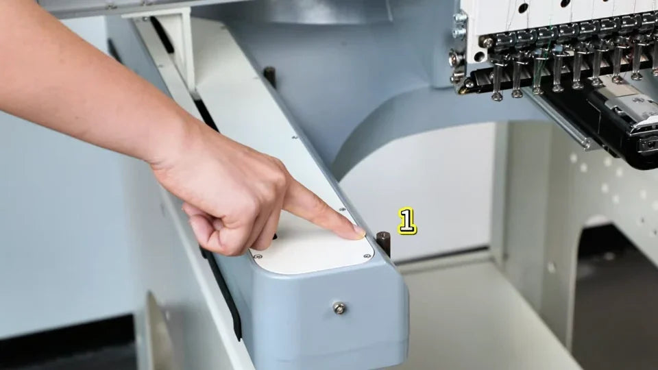
The presenter points to the front mounting point on one inner arm.
The two numbered points on the opposite arm show the front and rear positions.

8. Slide the tabletop into place and check its height

Watch at 01:48

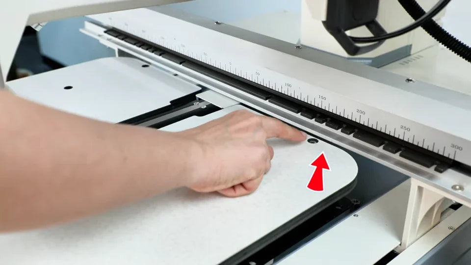
With the slot toward the machine, support the assembly from the front and slide it inward beneath the embroidery head as shown. Sight across the adjoining surfaces. The tabletop should sit slightly below the metal plates on the machine.
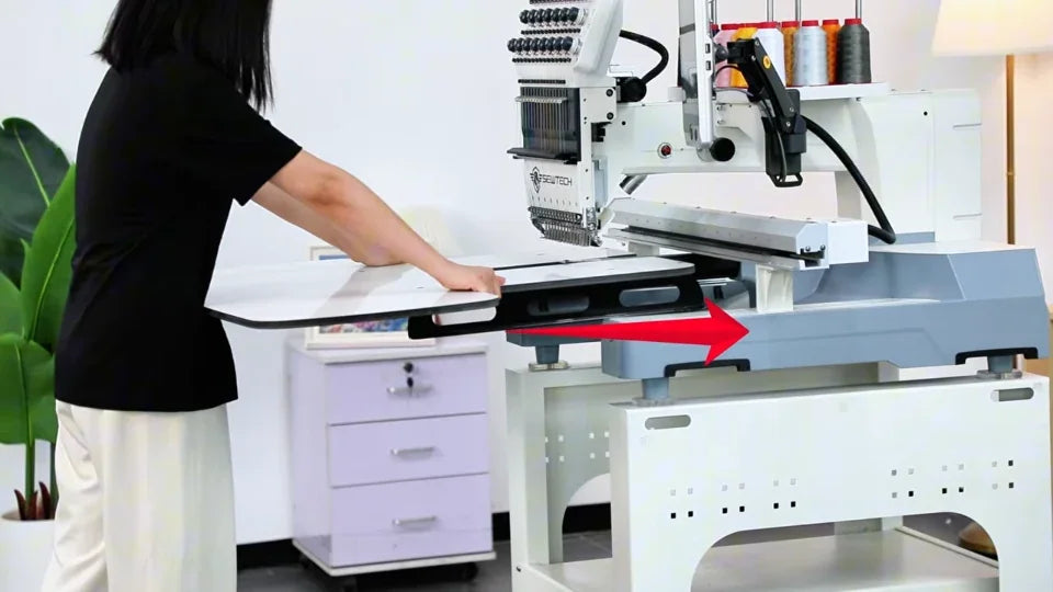
The red arrow shows the table sliding toward the machine.
Use the metal surface on the machine, immediately above the tabletop edge, as the height reference.

9. Line up all four bracket holes with the machine

Watch at 02:04

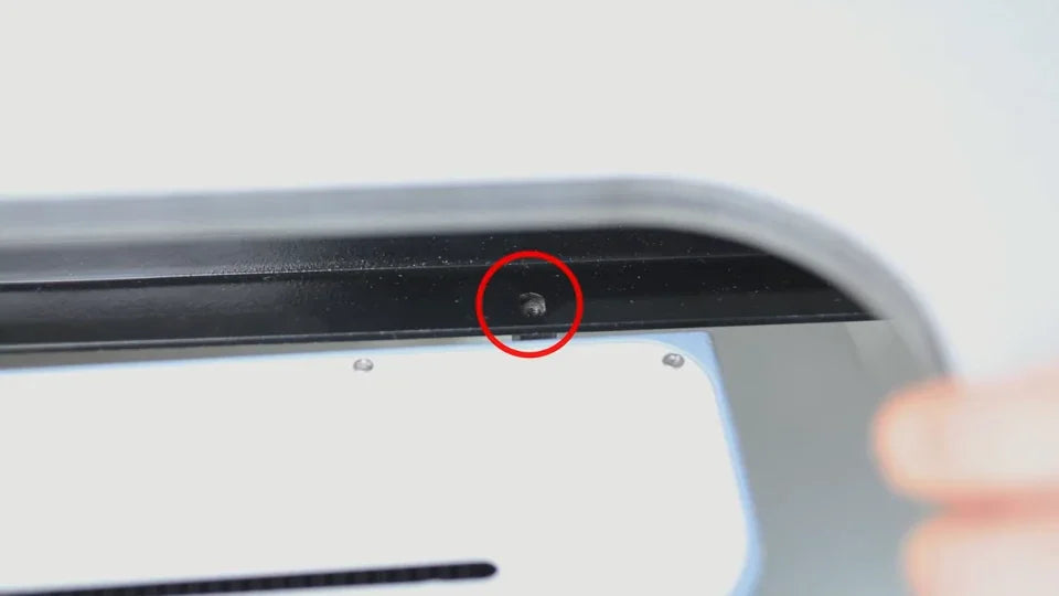
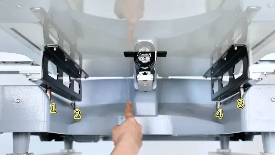
Look underneath to find the holes in the lower flanges of the two brackets. Adjust the table position until both holes on each side sit directly over their matching machine mounts. Check all four before inserting the screws.
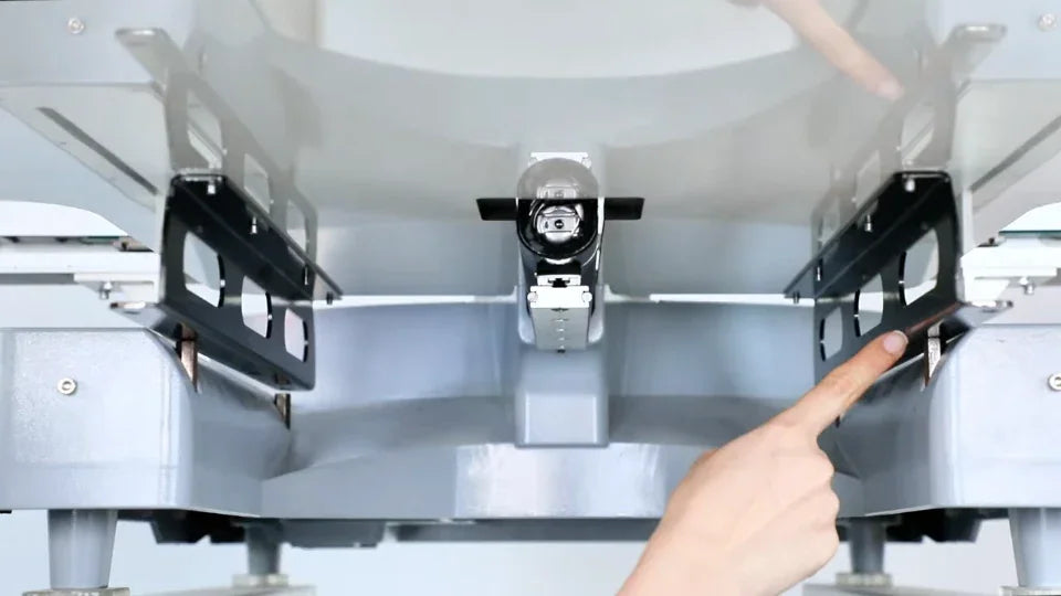
From below, the presenter points to the lower flange of the black bracket.
The underside view numbers the four corresponding mounting points.
The red circle marks an aligned hole in the lower bracket flange.

10. Insert all four machine mounting screws

Watch at 02:40

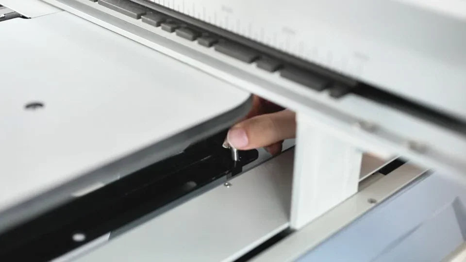
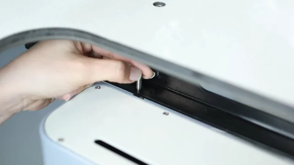
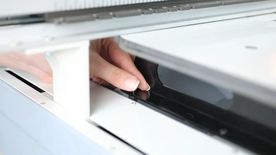
Use the four screws shown for fastening the bracket flanges to the machine. Reach beneath the tabletop and start each screw by hand, down through a bracket hole into its matching mount. Check that all four have caught before tightening any fully.
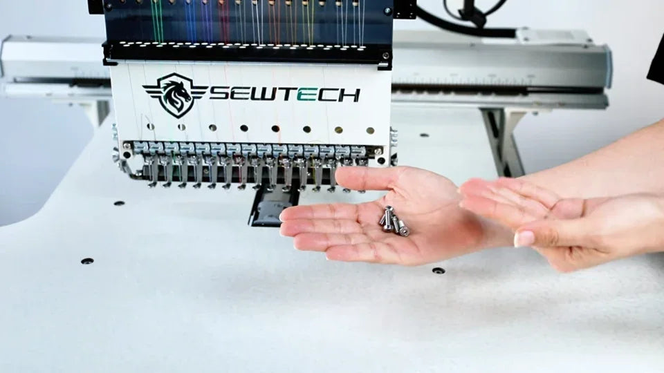
Use these four screws to fasten the table to the machine.
Start a screw by hand through the lower bracket flange.
Reach beneath the tabletop to start the screw farther in.
The presenter starts the screw on the other side before tightening any of the four.

11. Tighten the four machine mounting screws

Watch at 03:06

Once all four screws are in place, use the L-shaped hex key to tighten each one securely. Fit the short end into the screw where the tabletop limits overhead clearance. Reach under the tabletop to get to the inner screws, as shown.
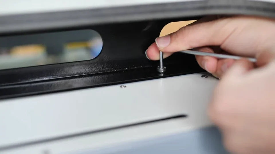
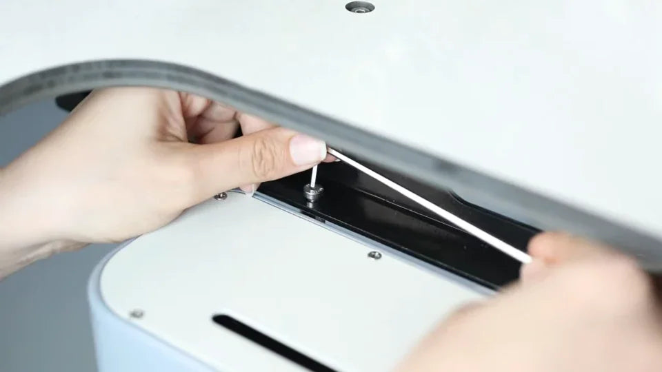
Engage the screw in the black flange with the short end of the hex key.
The long arm clears the edge as the presenter turns the screw.
Reach farther underneath to tighten the inner mounting point.

12. Check the installed table for movement

Watch at 03:22

Confirm the table is seated with its surface slightly below the machine plates and all four mounting screws tight. With the machine stopped, lightly check the front edge for rocking. The video ends with a view of the installed tabletop and a spoken stability check.
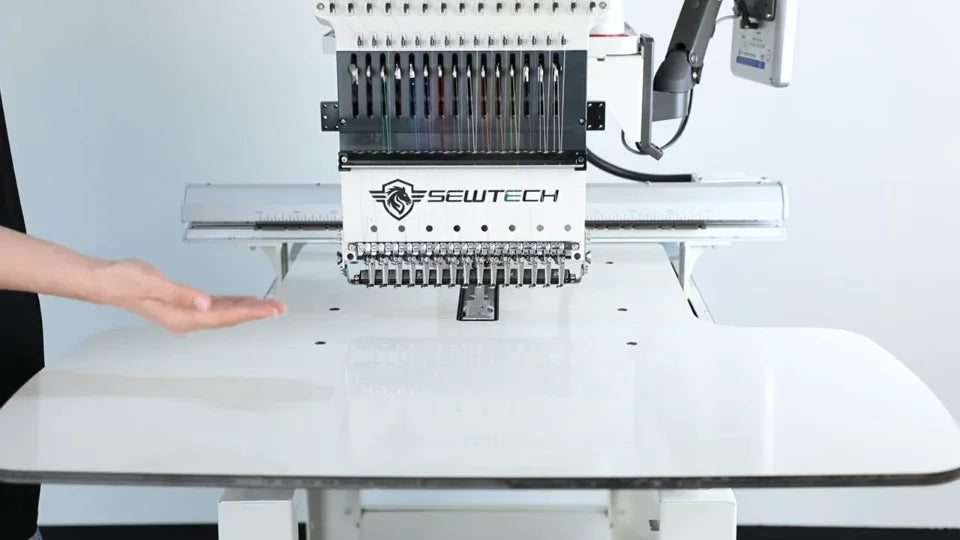
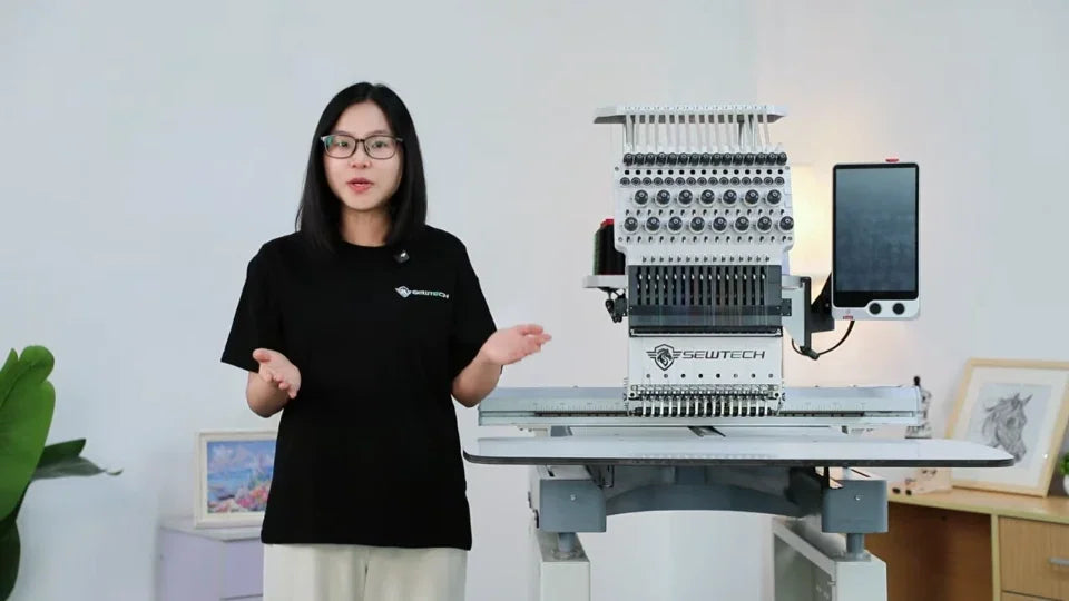
From the front, the center slot sits around the machine arm and both sides are in place.
The wide shot shows the completed table beneath the ST-1501 head.