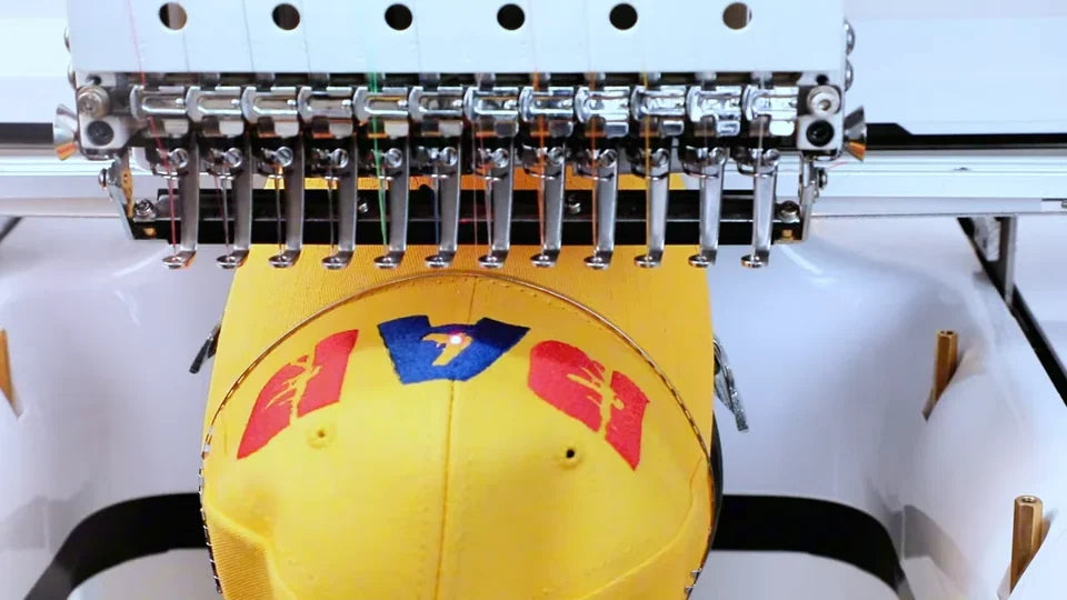
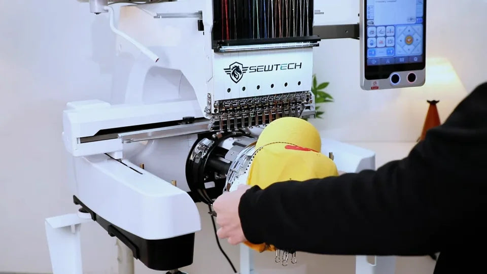
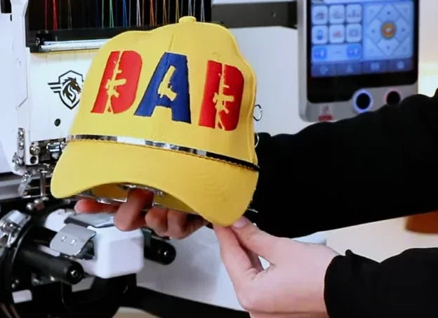
Embroider a Cap on the ST-1201 and SC-1501

Overview
Follow the full cap embroidery sequence, from securing the cap station to checking the finished design. The machine, mounting hole positions and touchscreen shown are from the ST-1201 demonstration. The guide also applies to the SC-1501. Check your own mounting points and installed cap frame before using the illustrated settings.
Step-by-step guide
1. Lay out the cap kit and supplies
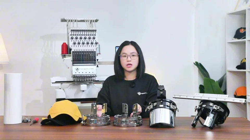
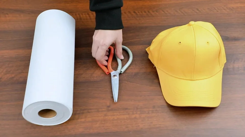
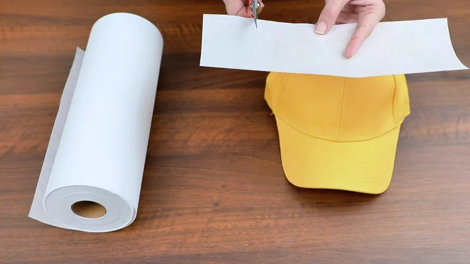
Watch at 00:22Gather the cap driver, cap station, cap hoop, cap, tear-away stabilizer, scissors, a screwdriver and four binder clips. The station holds the hoop while you load the cap. The driver mounts on the machine and moves the loaded hoop during stitching. The video shows two hoops so you can prepare a second cap while the first is sewing.
2. Clamp the cap station to the table
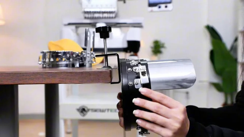
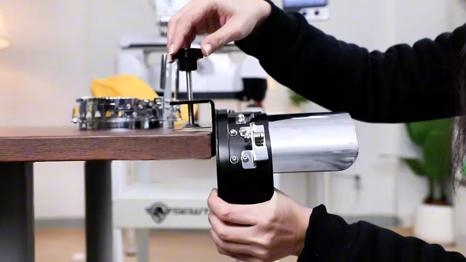
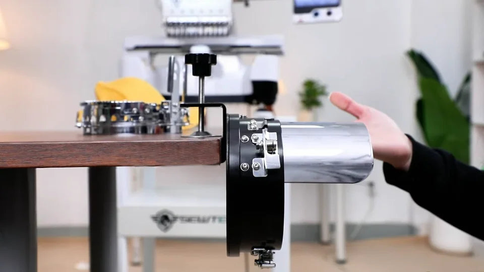
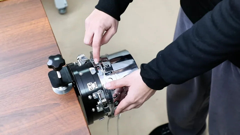
Watch at 01:17Choose a flat, rigid work surface. Turn the black clamp knob counterclockwise to open the clamp to the thickness of the tabletop. Slide it fully onto the edge until its inner face sits flush against the table. Tighten the knob, then gently rock the station to check that it stays put.
3. Fit the empty hoop onto the station
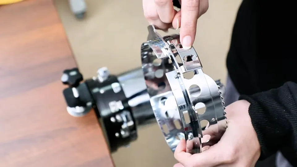
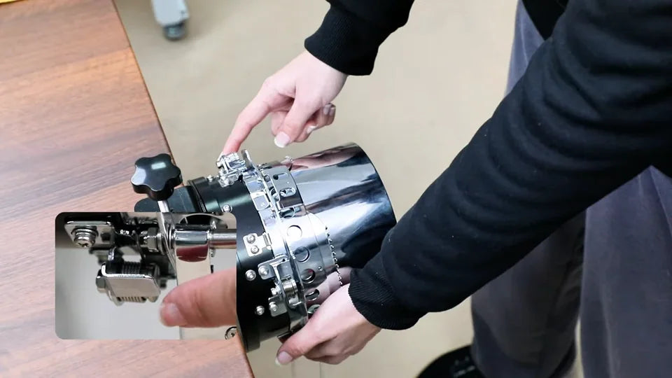
Watch at 02:02Open the retaining strap and swing it clear of your hands. Find the hoop latch and center mark, then slide the ring onto the station with the latch aligned to the locating block. Push evenly with both hands until it clicks. Check the two upper clips and the lower clip. To remove the hoop, press all three clips together and slide it off.
4. Cut and place the stabilizer
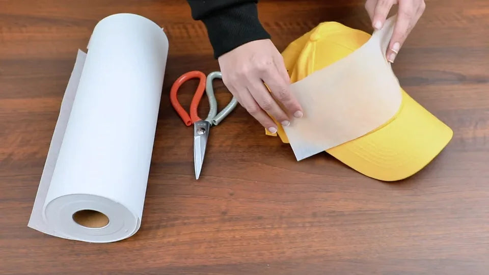
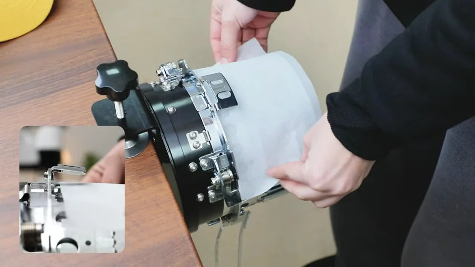
Watch at 03:00Cut tear-away stabilizer to cover the entire area you will stitch. This front-panel design uses a piece wide enough to back the whole front. Use a longer piece for side embroidery so the side stitching area is also supported. Lay the front-panel piece on the station over the installed hoop, under the area the cap will cover.
5. Turn out the sweatband and seat the cap
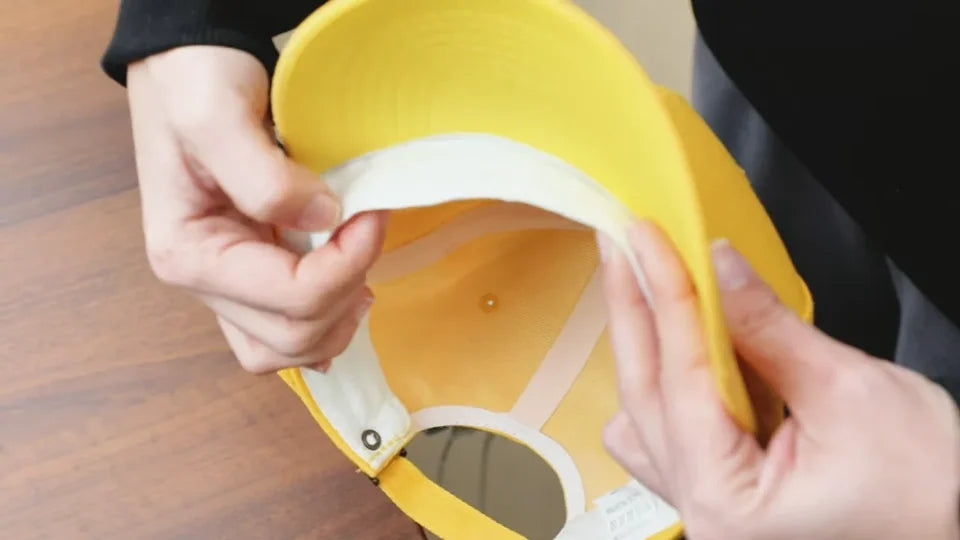
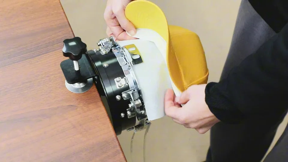
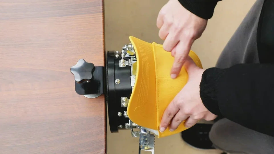
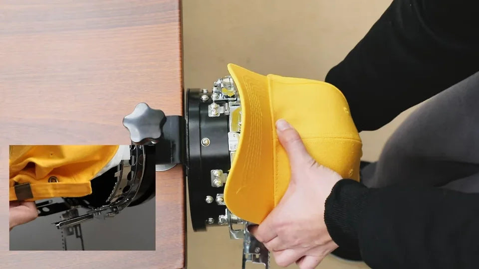
Watch at 03:52Turn the inner sweatband outward and slide it under the center section of the hoop. Match the cap’s front center seam to the hoop’s center mark. Smooth the sweatband over the hoop so it lies flat. Look behind the cap and check that the fabric extends over both rear supports.
6. Catch the lower edge and close the strap
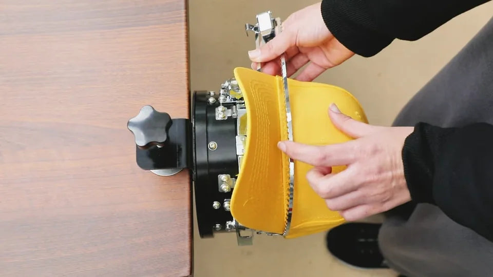
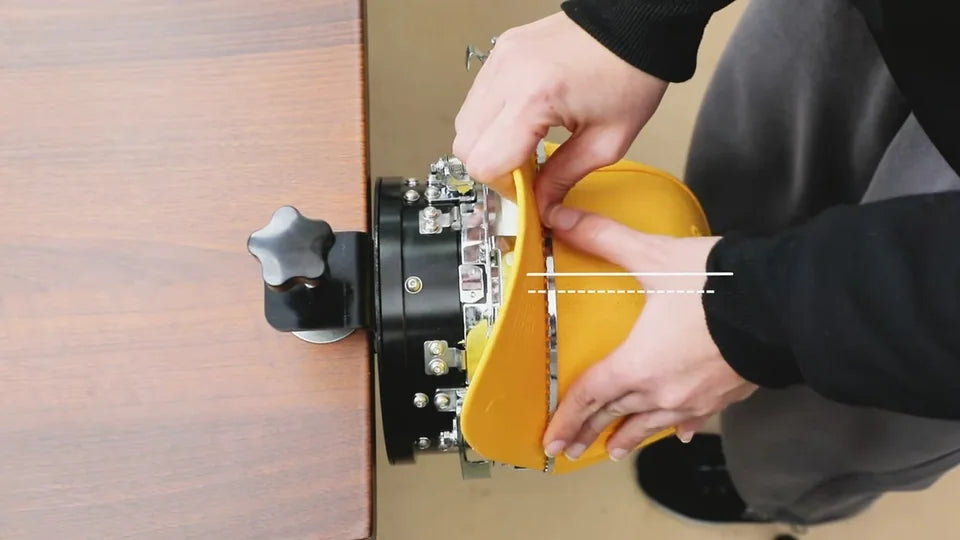
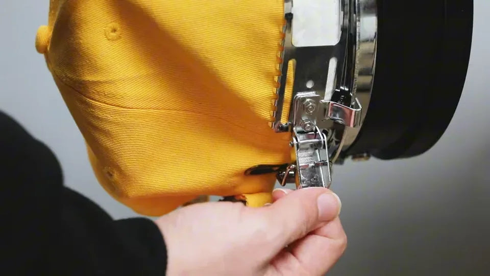
Watch at 04:25Bring the retaining strap over the cap and check that its edge catches the bottom of the front panel. Just before closing the latch, the demonstrator shifts the seam slightly to the left as viewed from above. Closing the strap pulls it back toward center in this setup. Recheck the seam against the hoop mark after the latch is closed.
7. Adjust the latch if it is hard to close
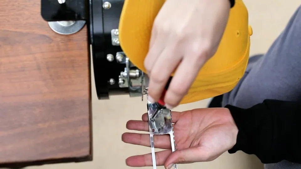
Watch at 04:57If the latch is hard to pull back, open it and slightly loosen the adjustment screw on the strap latch. Make a small adjustment, retighten the screw and try closing it again. The presenter calls the tool a wrench, and the close-up shows a screwdriver. Use the tool that fits your fastener. Confirm that the latch closes more easily, the cap is held firmly and the center seam meets the hoop mark.
8. Secure the back and release the loaded hoop
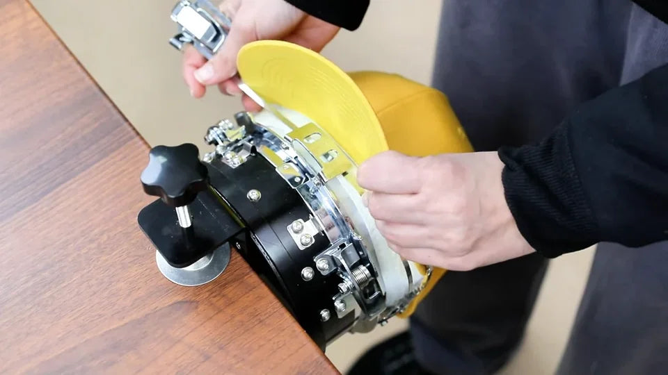
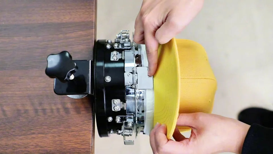
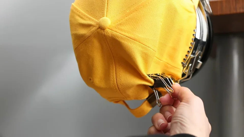
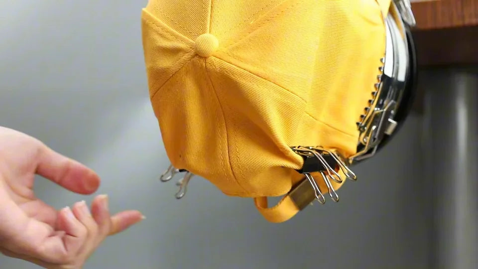
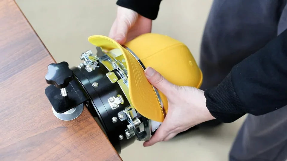
Watch at 05:37Use four binder clips to secure the loose fabric at the back, two on each side. Support the loaded hoop with both hands, press the station’s three release clips and slide the whole cap hoop off. The cap and backing stay in the hoop for transfer to the machine.
9. Switch off the machine and position the cap driver
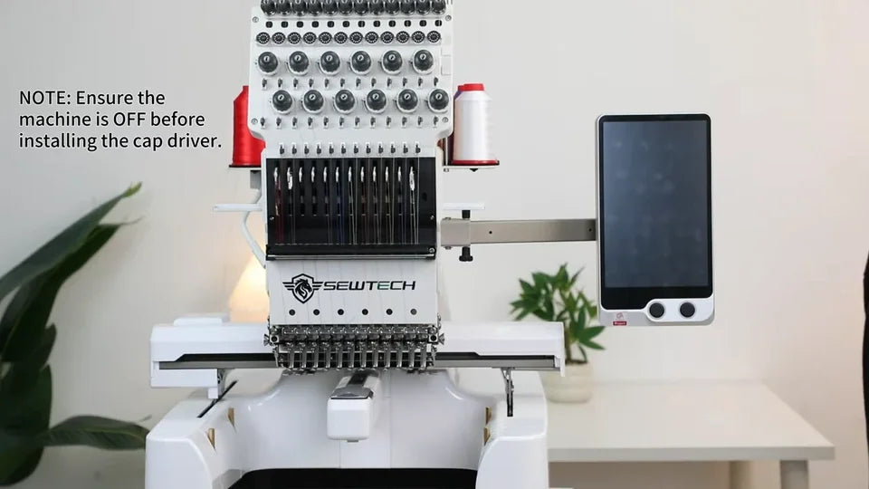
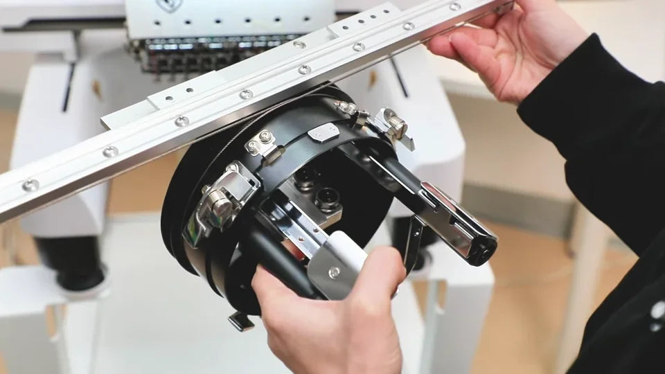
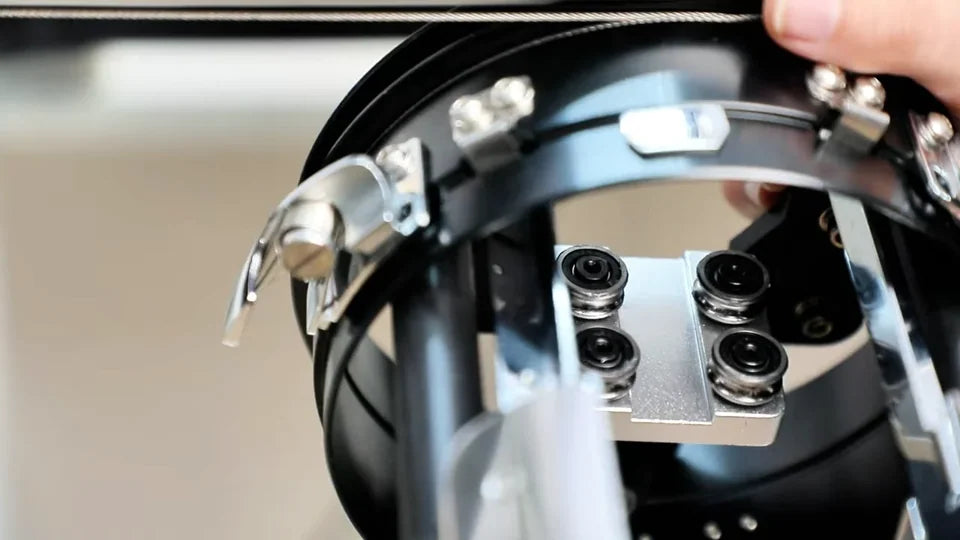
Watch at 06:02Turn the machine off at its power switch before fitting the cap driver. Once the screen is dark, support the driver with both hands and turn its ring into position beneath the needle head. Hold it centered with the crossbar level and its four guide rollers facing up.
10. Engage all four rollers with the rails
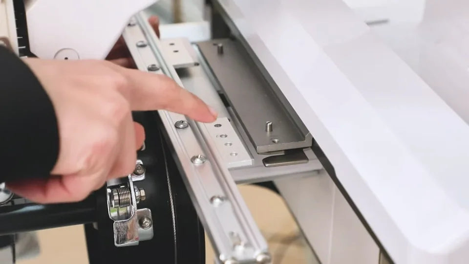
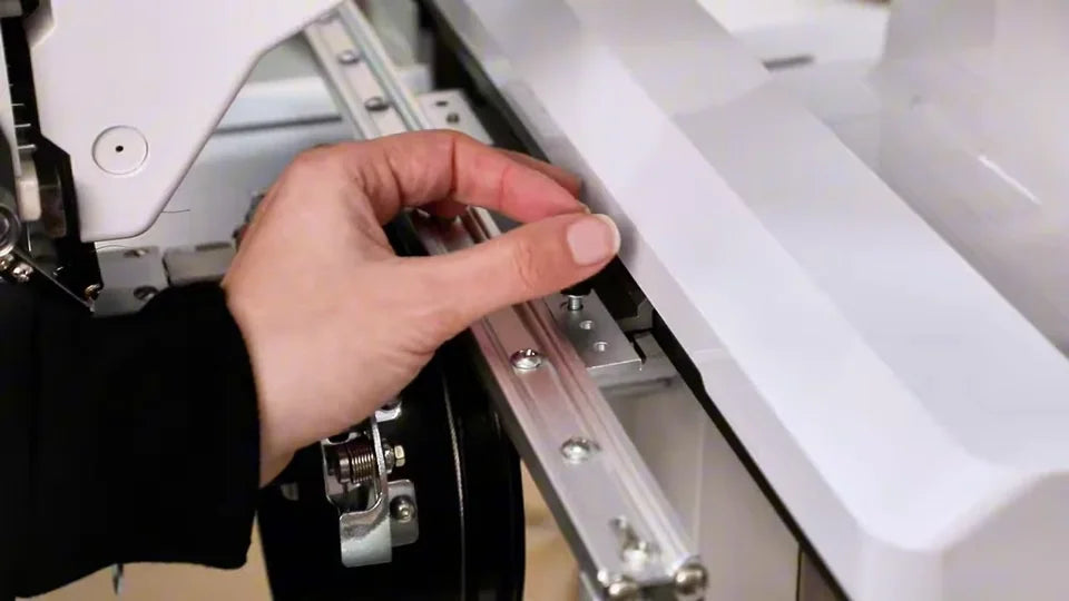
Watch at 06:42Align the rollers with both rails beneath the cylinder arm and slide the driver in evenly once all four rollers are on track. At the crossbar, place the driver’s lower plate between the two machine plates and rest the upper plate on top, as shown. Hold the assembly in place while lining up the fasteners.


11. Line up both mounting points and tighten the knobs
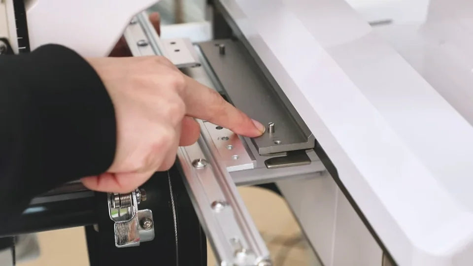
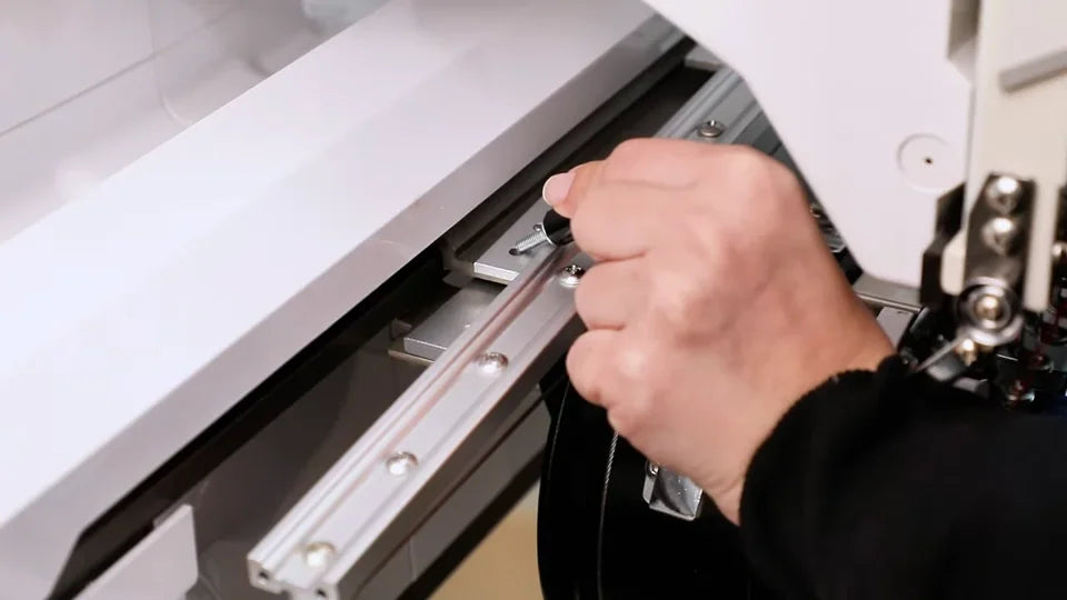
Watch at 07:10Match the bar’s locating holes to the protruding screws on the machine plate. On the side shown first, the end locating hole goes over the screw and the fastening hole lines up at the No. 2 position. On the opposite side, the demonstrator identifies the second locating hole and lines up the remaining fastening hole. With both sides seated, insert the two black threaded knobs and tighten them securely. The hole positions shown are for the filmed ST-1201 setup.

12. Power on and select Cap Frame immediately
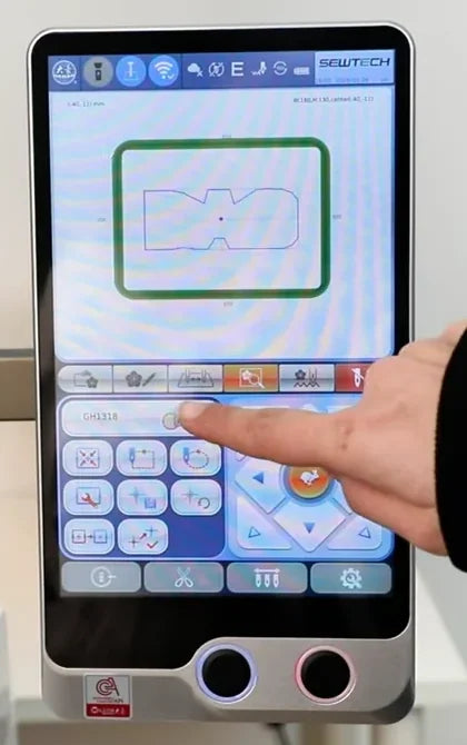
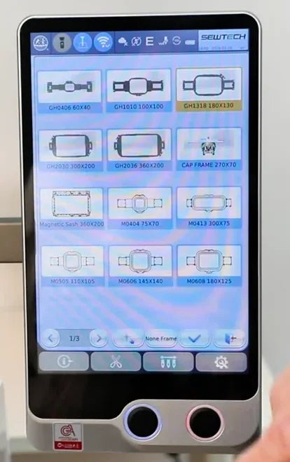
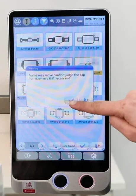
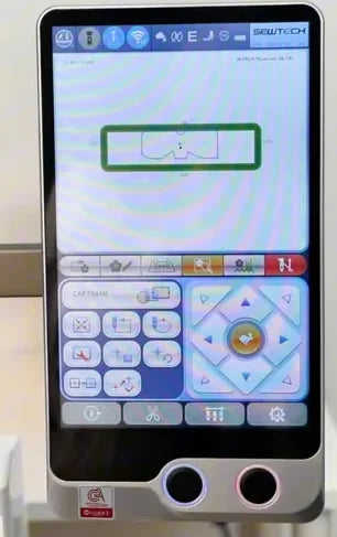
Watch at 07:59With the driver fixed and the loaded hoop still off the machine, turn the power on. As soon as the touchscreen is ready, open the frame positioning view and tap the current frame name on the left below the preview. The video uses CAP FRAME 270X70, on the right of the second row. Tap the checkmark. Read the frame movement warning, keep the area clear and confirm. The preview switches to a long, narrow green frame outline.
13. Check the bobbin and mount the loaded hoop
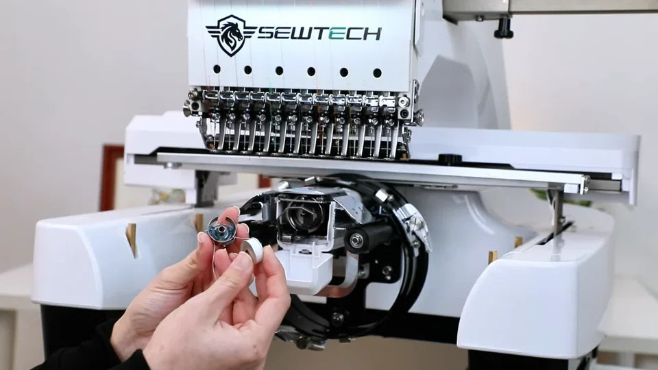
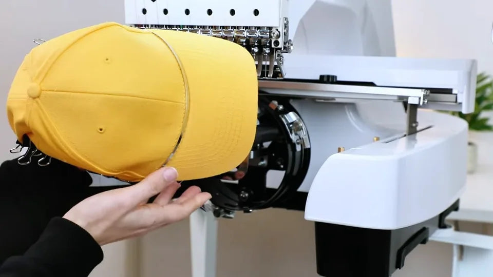
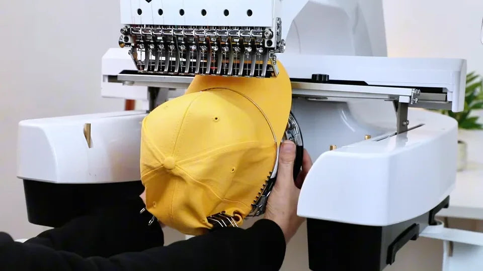
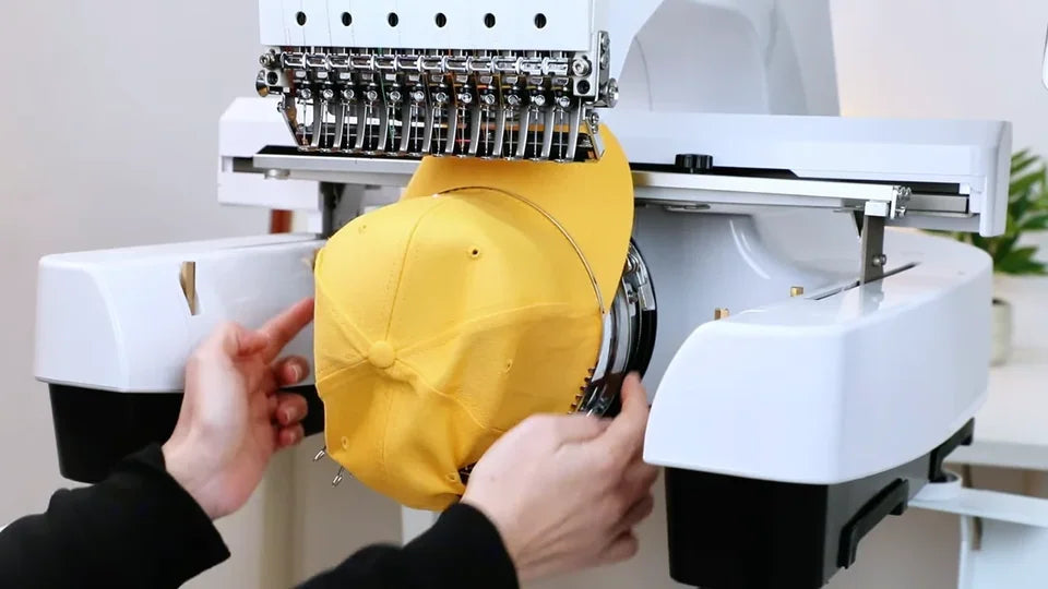
Watch at 08:24Before blocking access with the cap, check the bobbin under the cylinder arm. Fit a full bobbin if the thread is running low, as in the demo. Approach the driver with the brim turned to one side, slide the hoop in and rotate it until the brim points up under the head. Push both sides evenly and check that all three driver clips lock.
14. Select the design and check the color sequence
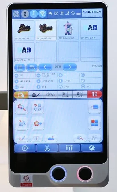
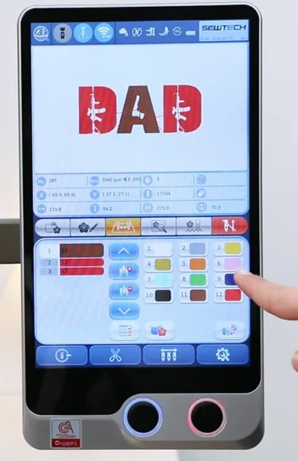
Watch at 09:02Choose the design thumbnail in the controller’s design list. Open the thread color screen using the spool-and-needle icon in the middle toolbar and assign a thread to each segment in stitch order. In the video the first color is reassigned to blue and the remaining colors follow the displayed sequence. Before proceeding, check the on-screen order against the thread actually fitted on the machine.
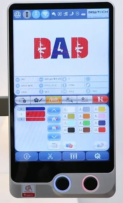
15. Center the design within the cap frame
Watch at 09:36Open the positioning preview and use the arrow pad on the right to move the design. In this view the design area is filled red and a warning triangle appears when it extends beyond the allowed boundary. Move it back until the valid green view returns. Center it for the front of the cap, then verify the placement on the actual cap by tracing.
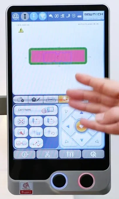
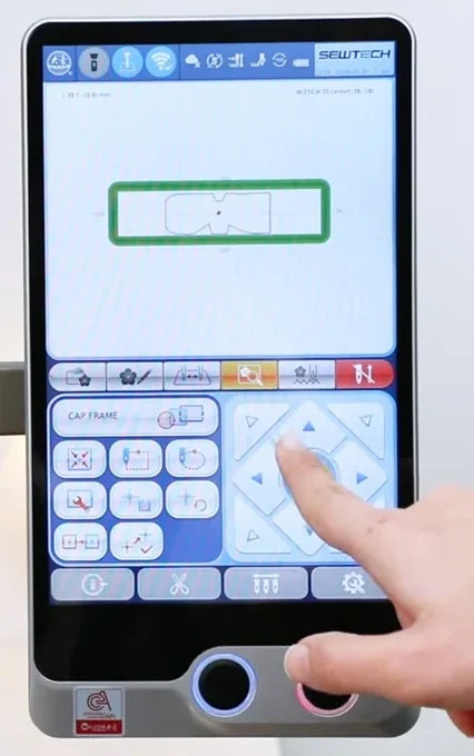
16. Trace with needle No. 1 and recheck the seam
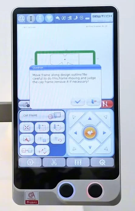
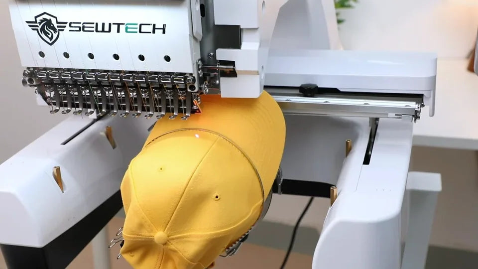
Watch at 10:13Open the needle selector and choose needle No. 1. The video switches from No. 6 to No. 1 for tracing. Return to the positioning view, tap the design-outline trace control and confirm the movement prompt with the area clear. Watch the actual needle position over the cap as the frame moves. Check that the outline stays on the intended area and clears the hoop. When the trace returns to the design center, check that No. 1 lines up with the cap’s front seam. The red laser dot is visible in the video, but its position is offset on this curved cap. Judge by the needle itself.
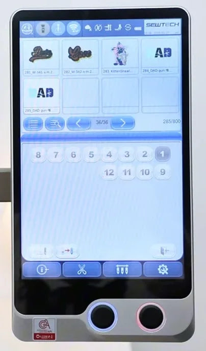

17. Set the speed, confirm the design and start
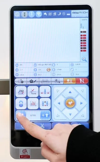
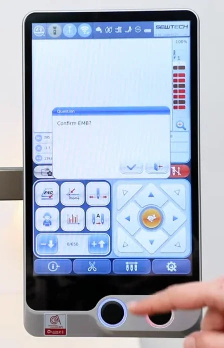
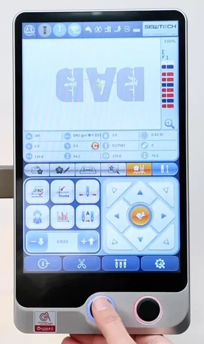
Watch at 11:30Open the stitching view and use the speed minus or plus controls at the lower left. The example lowers the set speed from 700 to 650 stitches per minute, shown as 0/650 while idle. Tap the red embroidery confirmation control at the right of the middle toolbar, then tap the checkmark in “Confirm EMB?”. Once ready, press the left physical Start button below the screen and watch the first stitches land in the traced area.
18. Remove the hoop and inspect the finished cap
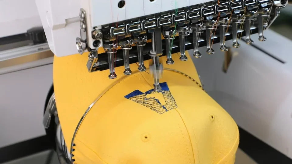
Watch at 12:21Wait for stitching and machine movement to stop. Support the hoop, release it from the driver and turn the brim to the side to clear the needle head as you slide it out. Check the front of the cap after removal. The demo shows the finished design centered on the front seam, with the intended colors complete.