Center a Magnetic Hoop on the ST-1501

Overview
Calibrate the center of an installed magnetic hoop on the SEWTECH ST-1501. Have the hoop with its mounting arms, a piece of fabric, a ruler and a washable fabric pen ready. You will mark the physical center, measure the laser offset, update the hoop profile and verify the result by reselecting it.
Step-by-step guide
1. Secure a piece of fabric in the hoop
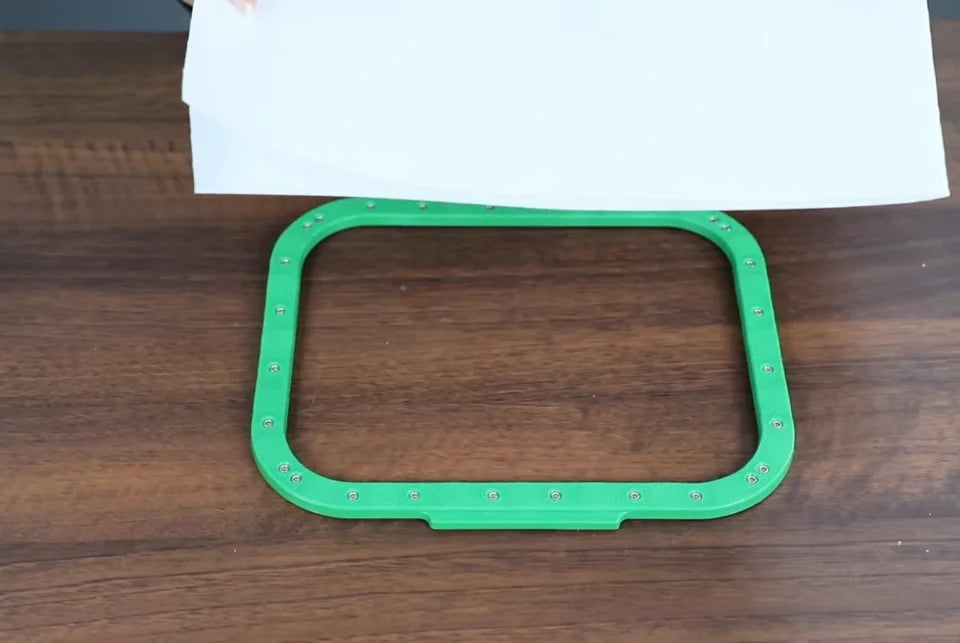
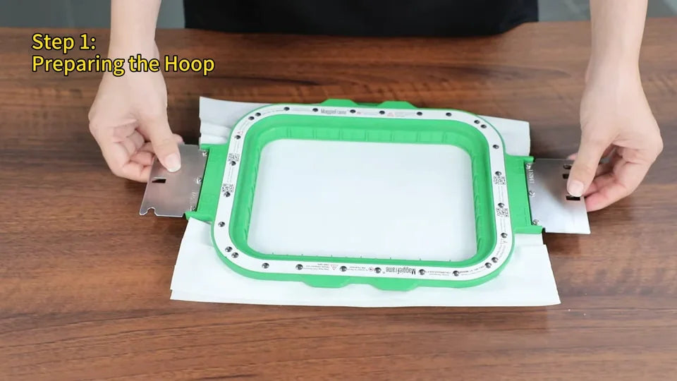
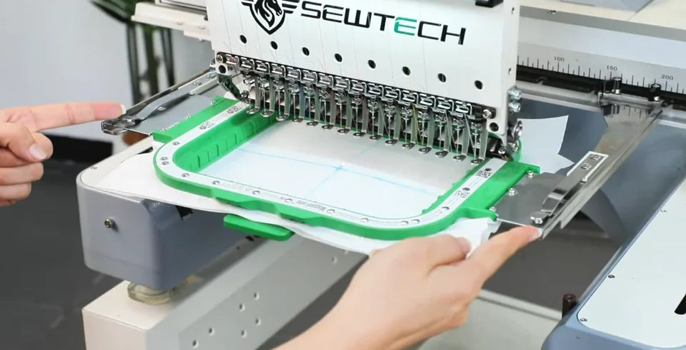
Watch at 00:09Set the lower magnetic ring flat on the table. Lay a piece of fabric over the opening, smooth it out, then lower the top hoop with its metal mounting arms onto the ring. Check that the fabric stays flat and held on all sides.
2. Measure the opening and draw a crosshair
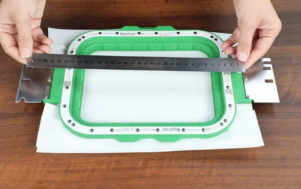
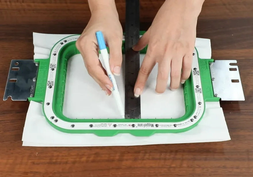
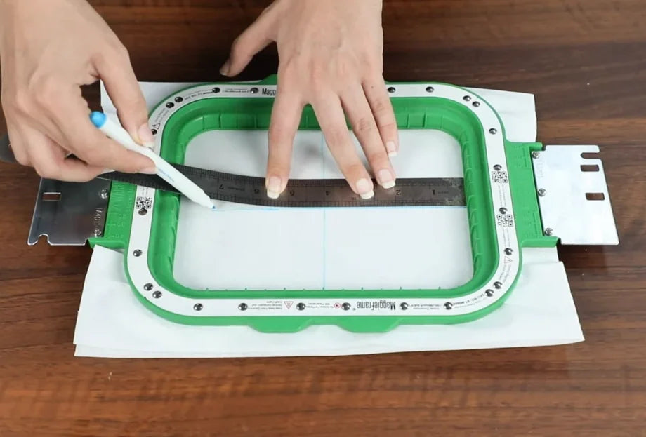
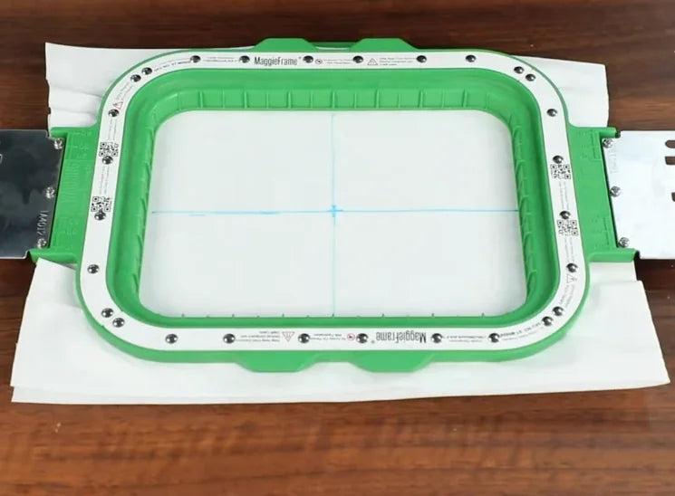
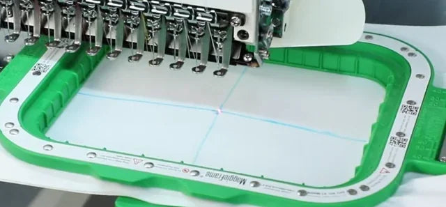
Watch at 00:18Use a ruler to find the midpoint along each dimension of the usable opening. With a washable fabric pen, draw a vertical line through the width midpoint and a horizontal line through the length midpoint. Their intersection is the physical center reference for the rest of the calibration.
3. Check the laser on the bare needle plate
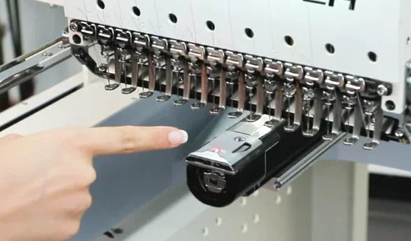
Watch at 00:42Before fitting the hoop, look under the needle head at the center mark on the metal needle plate. The red laser dot should line up with that mark before you use the laser to measure the hoop offset.
4. Seat both metal arms and check for play
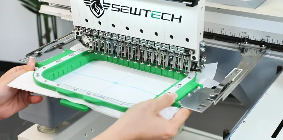
Watch at 00:50Bring the hoop in from the front with the crosshair facing up. Fit both metal arms into the matching carriage mounts and check both sides by hand. The hoop should sit securely without wobbling. Reseat an arm if it moves in its mount.
5. Switch to needle 1
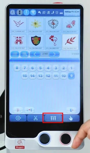
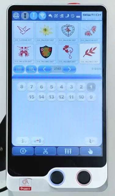
Watch at 00:59Tap the three-needle icon on the bottom touchscreen bar. Select 1 at the right end of the upper row of needle numbers. The 1 highlights and the needle head moves to that position.
6. Load the profile for the mounted hoop
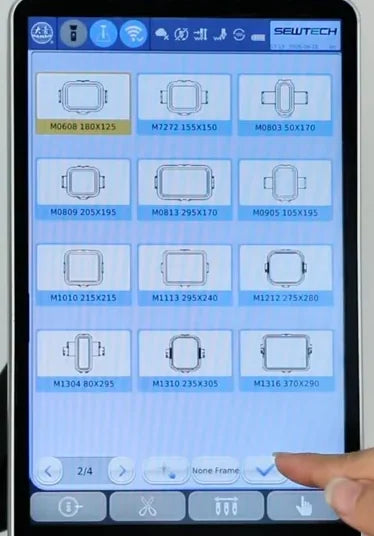
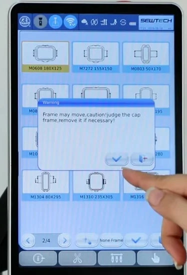
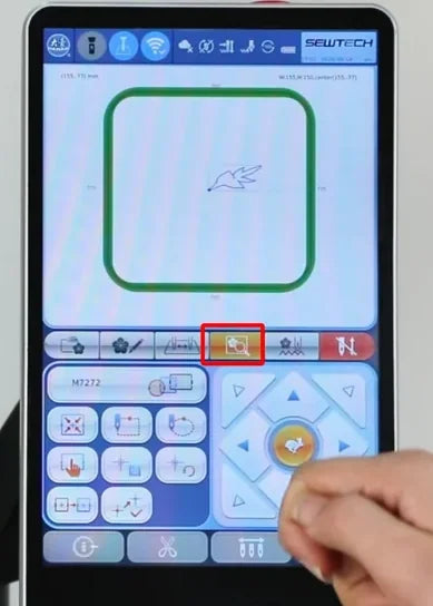
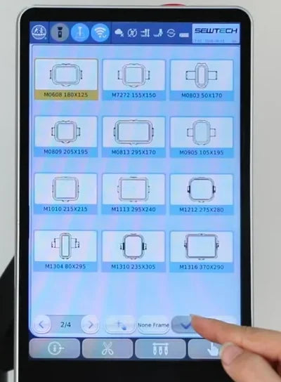
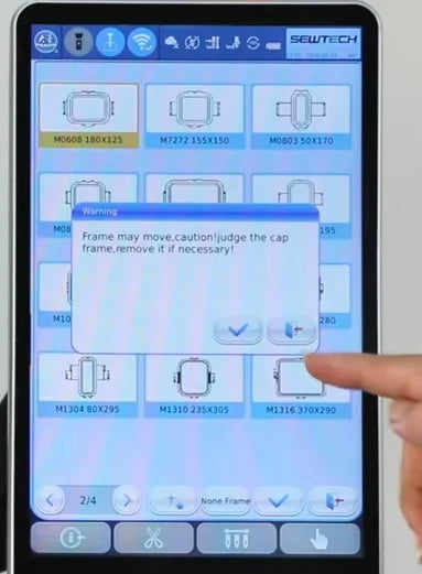
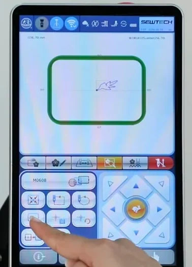
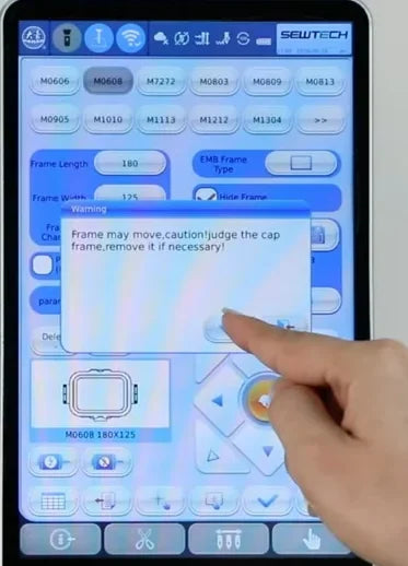
Watch at 01:08On the design preview, tap the gold hoop-selection icon below the design. Pick the card for the installed hoop. The demo uses M0608 180 × 125 at the top left of page 2/4. Tap the bottom checkmark. When the frame-movement warning appears, keep the path clear and confirm with the dialog checkmark. Let the carriage finish moving.
7. Check where the laser lands
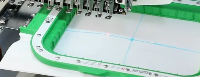
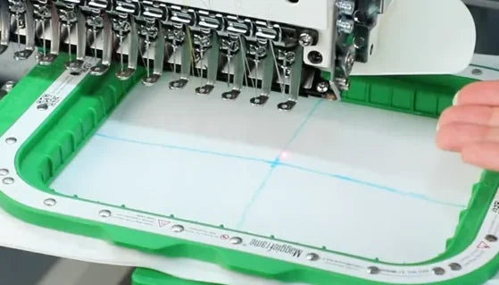
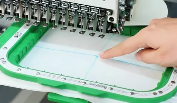
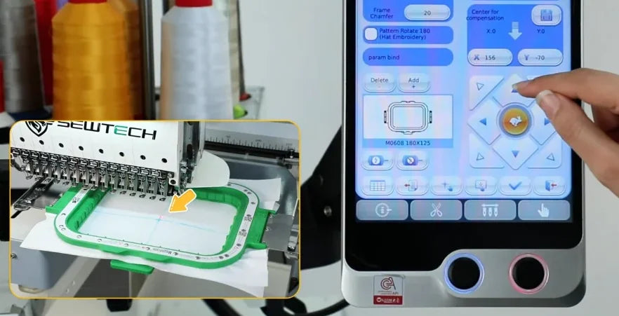
Watch at 01:25With the hoop stopped, compare the red laser dot on the fabric with the blue crosshair. In the demo the dot is slightly above and to the right of the intersection. Use the marked intersection as the target.
8. Open the frame parameter page
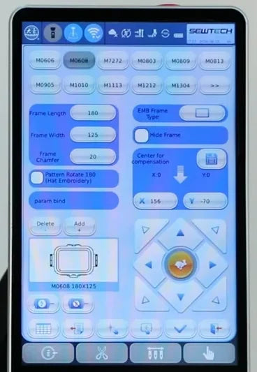
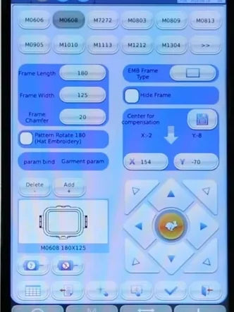
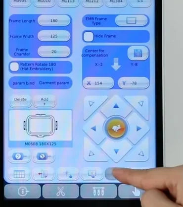
Watch at 01:31On the main hoop preview, tap the leftmost button of the second row in the grid of small controls beside the direction pad. On the parameter page, check that M0608 is the active profile in the demo and locate the right-hand “Center for compensation” panel above the arrows.
9. Jog the hoop until the laser meets the crosshair
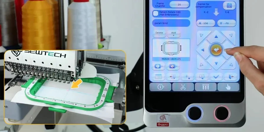
Watch at 01:34Tap the direction arrows on the right side of the frame parameters. Each tap moves the hoop beneath the laser. Watch the dot on the fabric as you jog and stop when it meets the blue intersection. Choose directions from what you see on your machine.
10. Read the measured offsets and stored values
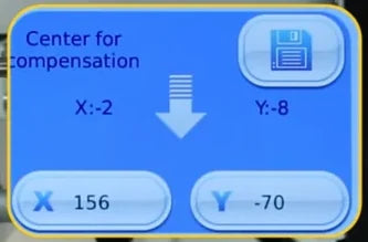
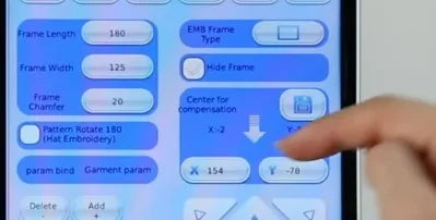
Watch at 01:44In “Center for compensation,” record the signed movement offsets in the blue area and the existing values in the two editable fields below. The video shows measured offsets X −2 and Y −8, with existing entries X 156 and Y −70. Add each signed offset to the existing value for that same axis. Use the figures from your own machine and hoop.
11. Enter the corrected X value
Watch at 01:57Tap the lower X field to open its numeric keypad. The demo adds −2 to 156 and enters 154. Tap the keypad checkmark, then check that the X field reads 154 in the example.
12. Enter the corrected Y value with its sign
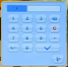
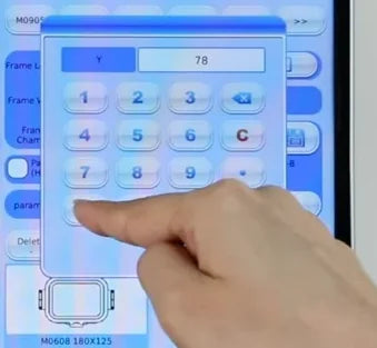
Watch at 02:08Tap the lower Y field. The demo adds −8 to −70 to get −78. Enter 78 and use the +/− key to make it negative. Confirm with the keypad checkmark and verify the lower Y field shows −78 in the example.
13. Save the updated frame parameters
Watch at 02:22Tap the checkmark on the frame parameter page, in the row just above the blue navigation bar. Confirm again in the warning dialog after checking the travel path. The design preview returns and the carriage moves. Once it stops, look for the laser at the marked center.
14. Temporarily select a different profile
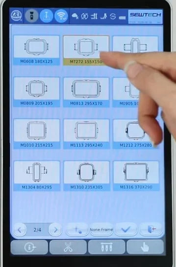
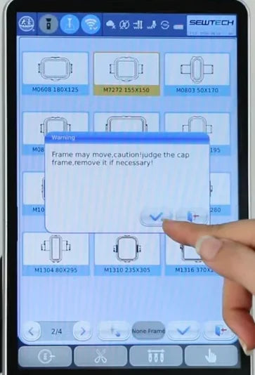
Watch at 02:36Reopen the hoop list. Keep the same physical hoop mounted for the check. The video temporarily selects the neighboring M7272 155 × 150 profile, taps the list checkmark and confirms the movement warning. Wait for the frame to stop before switching back.
15. Reselect the calibrated profile and verify the center
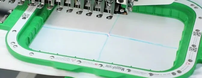
Watch at 02:49Open the list again, reselect the calibrated profile and confirm both checkmarks. The demo switches back to M0608. Watch the mark after the last carriage movement has stopped. The saved center is verified when the laser returns to the intersection. If the dot is still off on your machine, check the frame seating and selected profile, then remeasure the offsets.