Check a Needle Hitting the Rotary Hook on the ST-1501

Overview
This SEWTECH ST-1501 tutorial covers a specific needle strike caused by a displaced bobbin case holder. Prepare the L-shaped hex key for the cover and a flat-blade screwdriver for the two position-plate screws. Use the handwheel to verify the needle’s path before powering the machine back on.
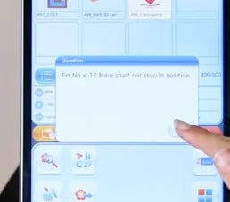
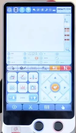
The video confirms two results. The needle clears the opening during the manual check, and the Error 12 popup clears after the 100° reset on the panel shown.
Step-by-step guide
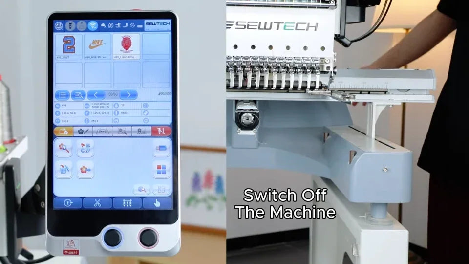
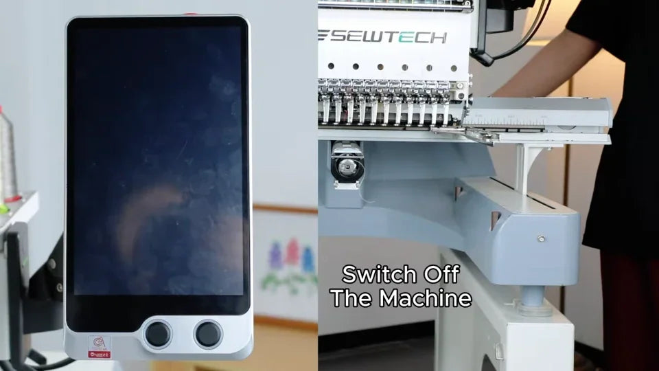
1. Switch off the machine
Watch at 00:21Switch off the ST-1501 before reaching into the needle or bobbin area. Confirm that the touchscreen goes dark. Keep the machine off through the adjustment and both handwheel checks.
2. Remove the needle plate cover
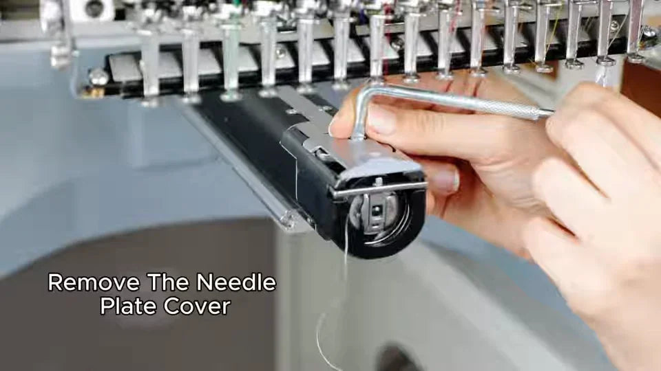
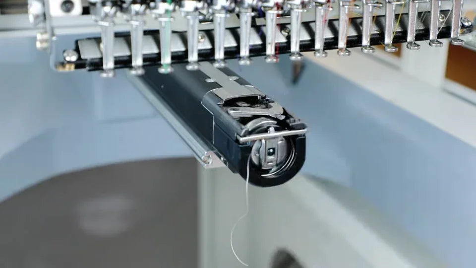
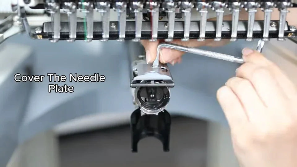
Watch at 00:23The small metal cover sits on top of the narrow arm directly below the needle row. Undo its fastener with the L-shaped hex key shown, then lift the cover away to expose the top of the hook area.
3. Take out the bobbin case with the bobbin inside
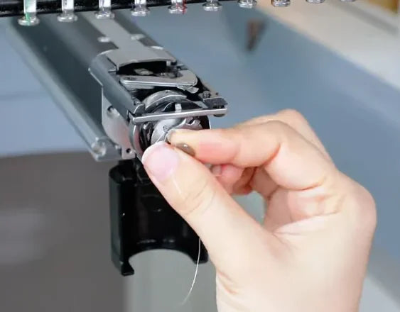
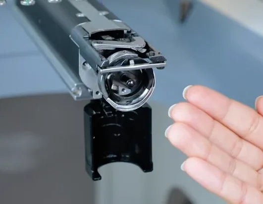
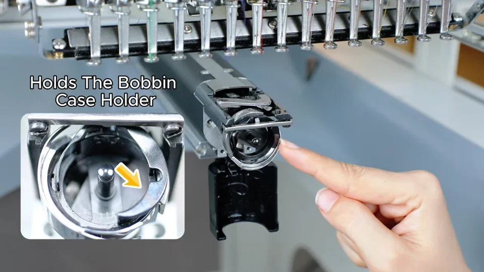
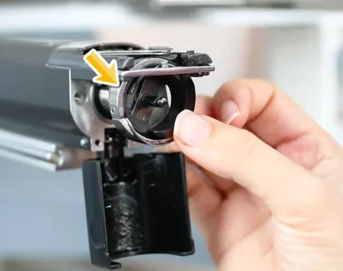
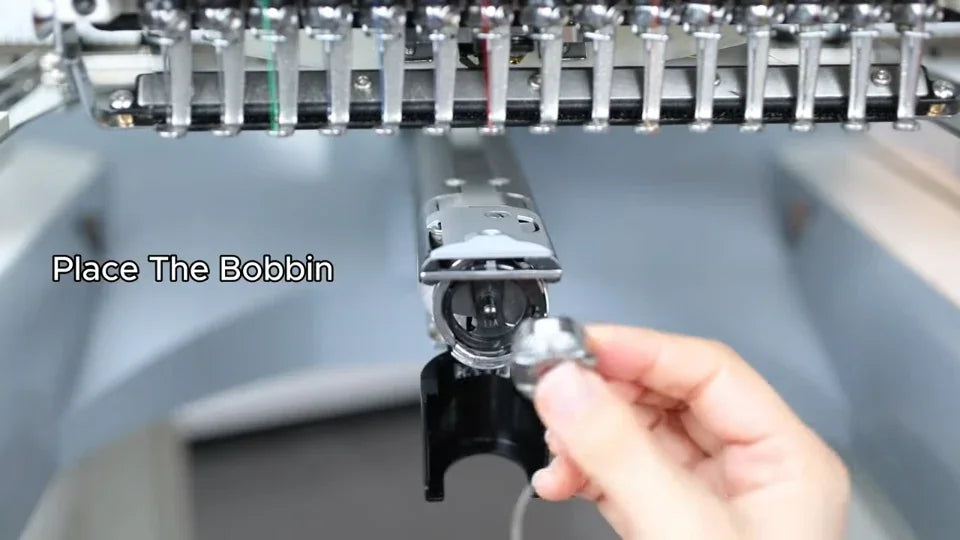
Watch at 00:28Open the black flap at the front of the narrow arm. Pull the bobbin case forward by its latch, with the bobbin still inside. The round bobbin case holder stays in the machine and is now visible.
4. Identify the position plate and the needle opening
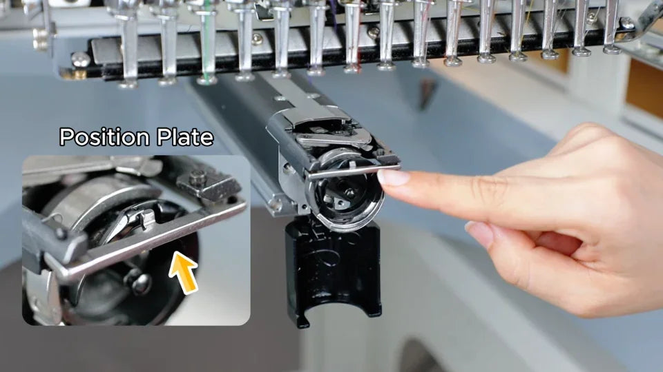
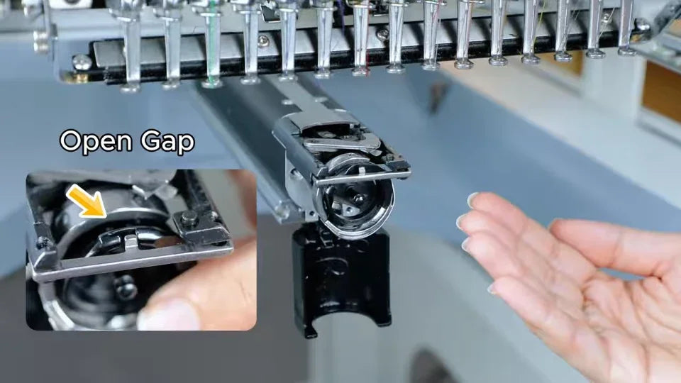
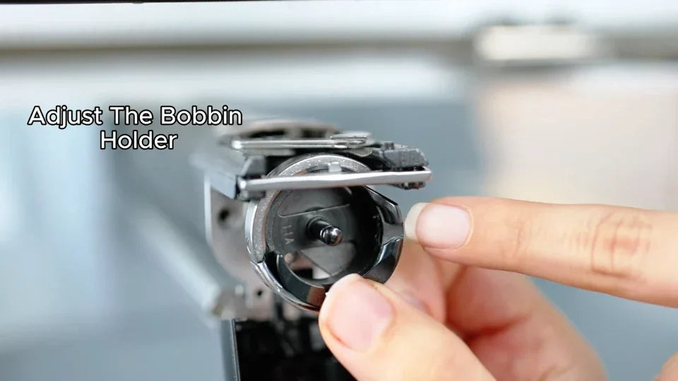
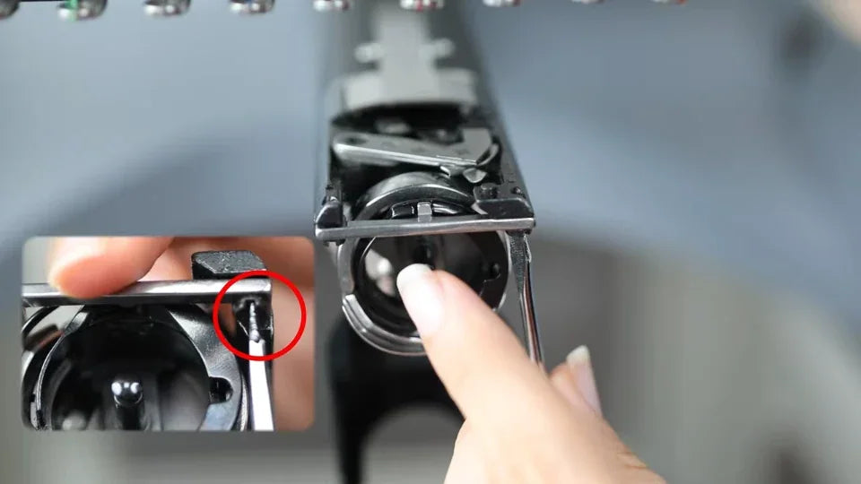
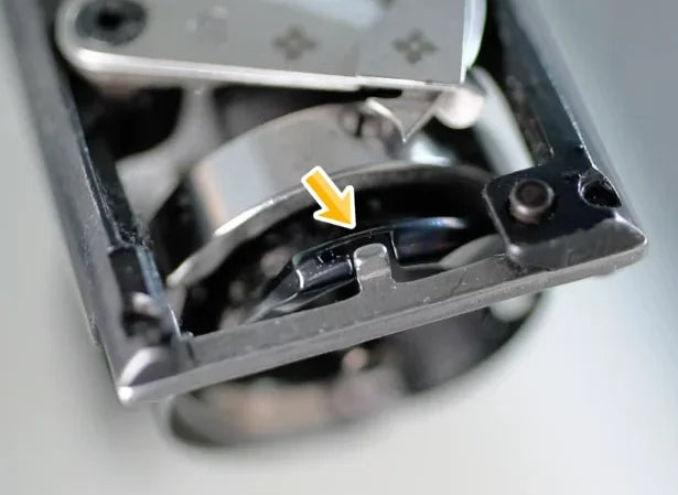
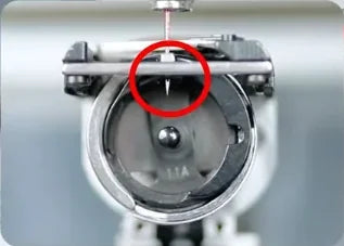
Watch at 00:32Find the thin position plate across the top of the round hook opening. Its small metal tab engages the notch in the bobbin case holder to keep the holder from twisting. A loose or displaced plate lets the holder turn, moving solid metal into the needle’s path.
5. Locate the contact point with the side handwheel
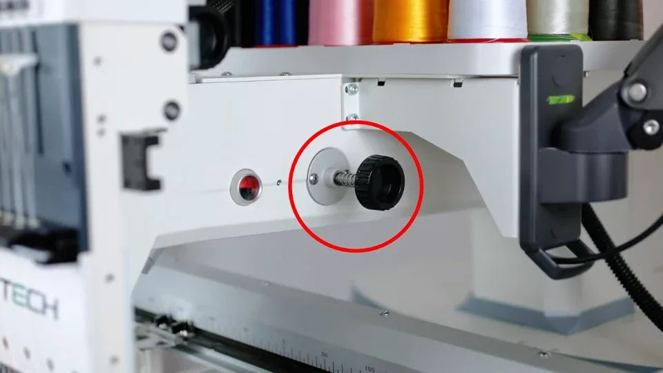
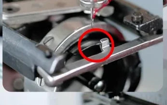
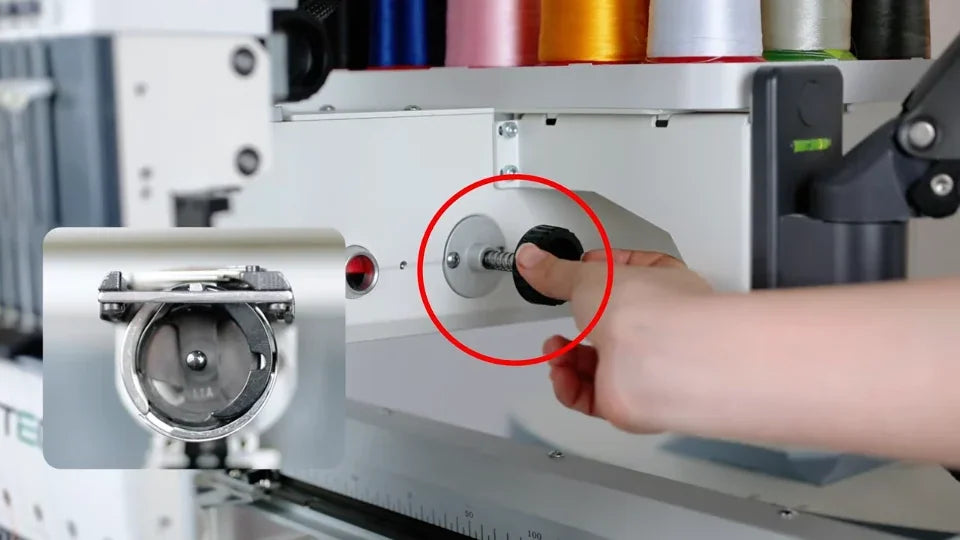
Watch at 00:58With the machine off, turn the black side handwheel beside the red window slowly by hand. Watch the needle approach the hook area. In the fault example, the needle meets solid metal beside the opening. If you feel contact, stop turning and raise the needle clear before moving the holder. The video warns that running at speed in this condition can break the needle.
6. Loosen both position-plate screws slightly
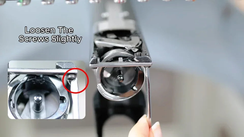
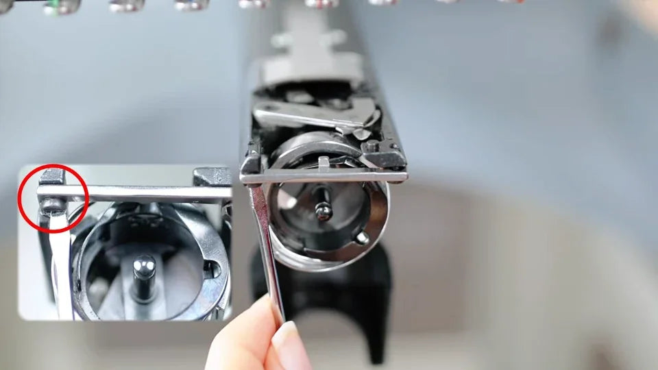
Watch at 01:22Use a flat-blade screwdriver on the two position-plate screws, one at each end of the plate above the circular opening. Loosen each screw just enough for the plate to slide. Leave both screws in place.
7. Rotate the holder until its slot meets the tab
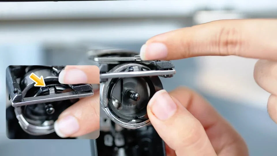
Watch at 01:31Gently turn the exposed bobbin case holder by hand. Bring the notch at its top into line with the small metal tab on the position plate. Use the notch and tab together as the reference for the next adjustments.
8. Line up the two inner edges
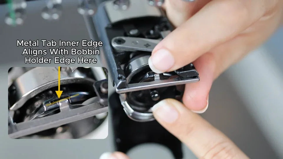
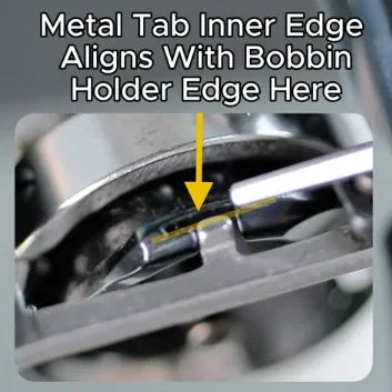
Watch at 01:42Look down into the top of the opening. Line up the inside edge of the metal tab with the inside edge of the holder at the notch. The yellow line in the close-up shows which edges to compare.
9. Center the tab in the slot
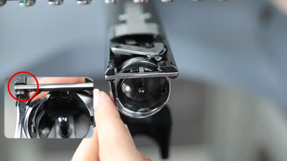
Watch at 01:51Slide the loosened position plate until the small tab sits in the middle of the holder’s slot. Look from above and check that the tab is centered between the two sides of the slot while the inner edges remain aligned.

10. Snug the screws and check the holder for movement
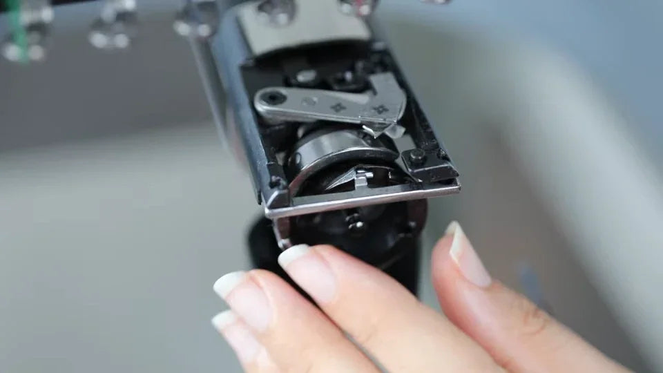
Watch at 01:58Lightly snug the screws to hold the position plate while you check the fit. Gently try to move the rim of the bobbin case holder by hand. Check that the tab still sits in the slot and that the holder stays in position before tightening fully.
11. Tighten both screws and retain the small opening
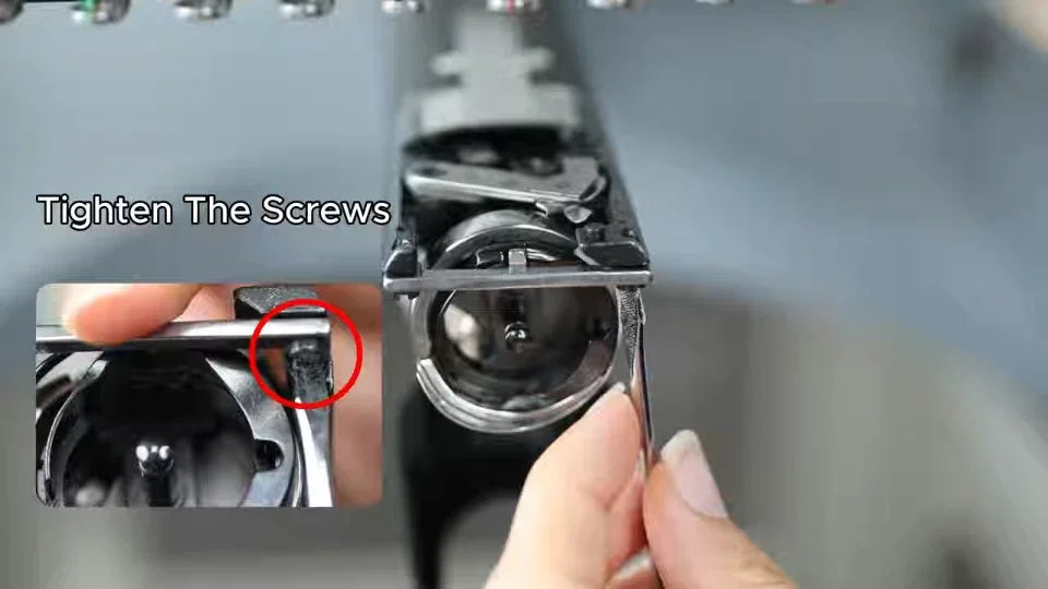
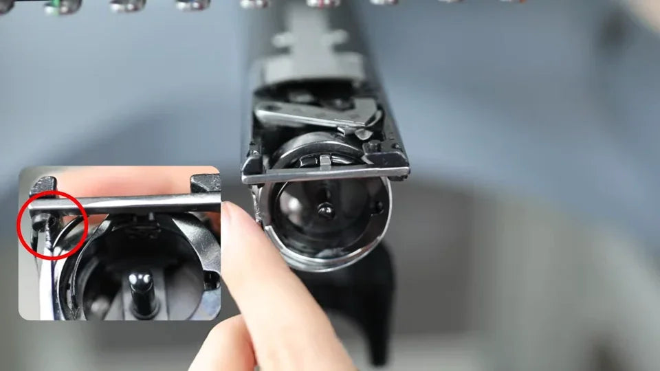
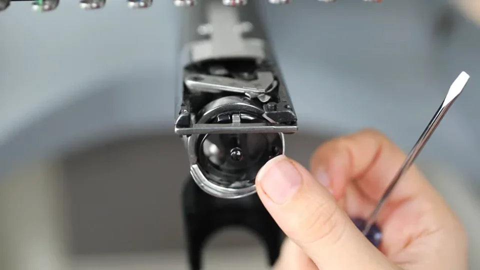
Watch at 02:06Finish tightening both position-plate screws. The holder should stay in position without wobbling while a small opening remains for the needle to pass. Use the close-up and the handwheel check to judge the fit. The video gives no numeric clearance or tightening torque.
12. Verify the needle passes through by hand
Watch at 02:20Keep the machine off and slowly turn the black handwheel again. Follow the descending needle at the hook opening. The adjustment passes this check when the needle travels straight through the gap without touching or deflecting against metal. Stop if it still catches before any powered test.
13. Refit the needle plate cover and bobbin case
Watch at 02:31Set the cover back on top of the narrow arm and secure it with the hex key. Push the bobbin case with its bobbin back into the front of the holder until it is seated. Close the black front flap before powering on. The video cuts to the startup sequence after showing the case seated.

14. Power on and read the startup message
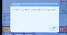
Watch at 02:39After reassembly, switch the machine on and wait for the main screen. The A15-pro panel shown in the video displays Error 12 after the handwheel check. The message says the main shaft did not stop in position. If it appears on your machine, follow the touchscreen reset below.

15. Clear Error 12 with the touchscreen’s 100° button
Watch at 02:47Dismiss the Error 12 popup using its lower-right control. On the main screen, tap the 100° button at the far left of the bottom toolbar, beside the scissors icon. Wait for the brief on-screen operation to finish and confirm the main screen is back with no Error 12 popup. The video ends after this confirmation.